Build your own Fourays
Fourays can be built as a 22HP eurorack module. The design here consists of one PCB and one front panel.
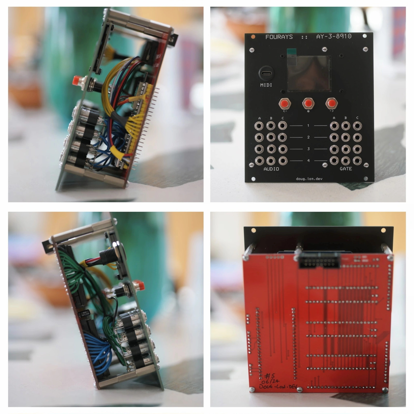
Bill of materials
| Item | Quantity |
|---|---|
| ESP32-S3 devkitc-1 | 1 |
| AY-3-8910 or YM2149F | 4 |
| DIN socket 40 pin | 4 |
| 1uF electrolytic capacitor | 4 |
| SPST push button | 3 |
| ST7735s SPI 160x128 display | 1 |
| USB A or USB C 4-lead socket | 1 |
| Eurorack 16 pin power header | 1 |
| 3.5mm audio sockets | 24 |
| M2 countersunk screws | 4 |
| M2 nuts | 4 |
| M3 F-M standoffs ~35mm | 6 |
| M3 dome head screws | 6 |
| M3 nuts | 6 |
| 26 AWG wire, various colours | - |
There are many variations of the ESP32-S3 devkitc-1 - you should find the version which has:
- 44 pins total
- 25.4mm horizontal pin spacing
The 3.5mm sockets and push buttons should be of the type which can affix to a panel with screw nuts, not PCB mountable ones.
You'll also need:
- some extra wire to connect all the buttons and sockets and screen to the PCB.
- some M2 screws and nuts to fix the screen to the front panel
- some M3 screws, standoffs and nuts to mount the PCB to the front panel.
Tips and hints for assembly
In no particular order;
Getting started
Complete as much of each board as possible before joining them together with wires.
Panel board
Mechanically assemble all of the parts to the panel before starting any of the wiring.
The audio sockets may need securing with some thread-lock on the inside of the thread, they may also need a dab of glue on the rear side for durability. Do the nuts up as tight as you can. You want the sockets to be secure because in normal use of the module, you'll be putting pulling and pushing forces on them as you re-patch your synth.
Try to align the common/GND pins of each row or column of sockets and buttons. This way you can run a single piece of bare wire across them and solder it in place.
The push buttons can be wired either way around. If you have cheap buttons, try not to overheat the pins during soldering, this can deform the case and internal parts and break them.
This version of the design omits a dedicated GND connection for the pushbuttons. Don't forget to run a wire from the button GNDs on the panel to any other available GND connection, for example to one of the sets of sockets.
Audio sockets typically have pin 1 = GND, pin 2 = signal and pin 3 is not used.
The screen usually has a removable plastic covering the display side. Remove this before assembling into the panel, but keep it and put it back on to the screen display to protect it during the rest of the assembly. You might need to trim it a bit so that you can place it in the display recess. Then finally remove it again when you have completed assembly.
If you are concerned about any tools you are using marking the panel surface during assembly, you can put some masking tape or sellotape on the panel surface first, and remove it when you've completed assembly.
Try not to place the panel face down on your table or bench during assembly, it could get quite dirty or damaged.
PCB circuit board
Start with the lowest profile components first.
With the board face-up and the printed text the right way up, assemble the 40 pin sockets with each pin 1 in the lower left position:

The ESP32-S3 does not use a socket, but instead 2 rows of 0.1" pin header. Put the longer side of the pins through the PCB, and the shorter side through the ESP32-S3 module. Align the ESP32-S3's wifi antenna over the white printed outline on the PCB, the USB-C ports point down. The directly attached USB-C ports are for programming only, they are not used as part of the synth instrument.
Put the AY chips into the sockets before you wire the two boards together. Pin 1 goes to the lower left corner, same as you did for the sockets.
PCB power selection
The PCB hosting the controller and AY chips runs on either the USB or the Eurorack 5V power supply.
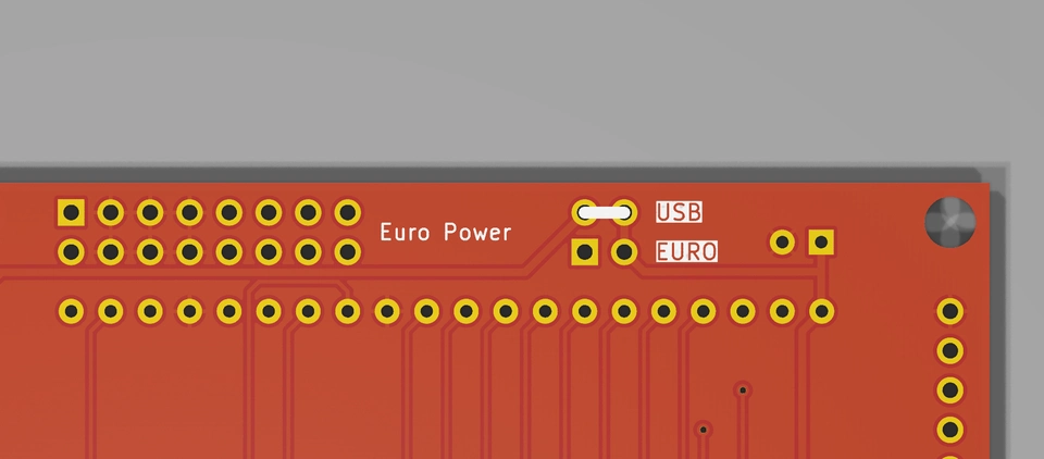
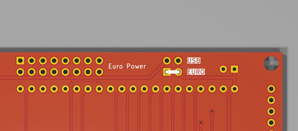
During assembly, choose to bridge EITHER the USB power input OR the Euro power input on the reverse of the board depending on where you want to source power from.
DO NOT CONNECT THE USB 5V POWER TO THE EURORACK 5V POWER SUPPLY
Using USB power:
Using Euro power:
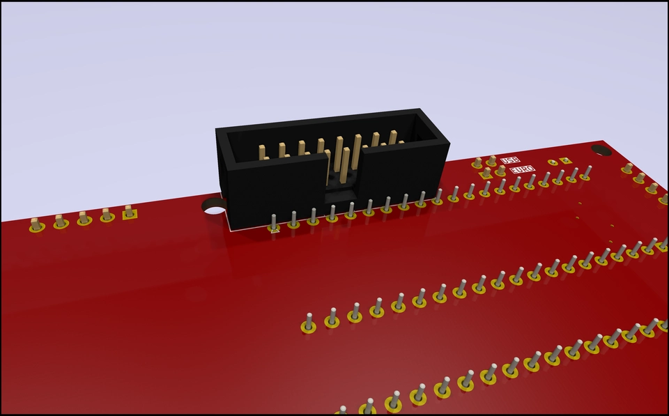
The Euro power connector attaches to the rear of the PCB with the cutout key notch facing towards the middle of the board:
Wire connections
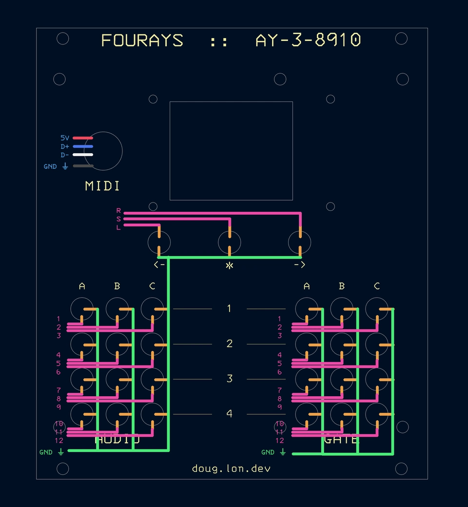
The ⏚ symbol represents ground, or GND.
For the Audio and Gate connections, use a different colour wire for each connection number 1 through 12, as you'll need to know which one is which later, after the wires have been bundled up. Don't forget the GND wire also. Don't forget that everthing is back to front when you are looking at the rear of the panel. You can use all the same colour wire, but its much harder to keep track of which one is which (you could use a multimeter to find and test each wire as you connect it). Attach the wires to the panel side components first. Put a couple of pieces of heatshrink tubing over each bundle of wires before you attach both ends, but don't shrink it just yet.

Attach all the wires to the PCB side as the last soldering operations you do. Attach the Gate and Audio wire bundles first and then fold the two boards together and then solder the remaining peripheral wires. The screen connections are labelled the same on the PCB and on the display module.
After attaching all of the wire bundles, arrange the wires neatly, but try not to crease/kink any of the wires or have any of the wires loop outside of the perimeter of the PCB. Finally slide each piece of heatshrink as far to opposite ends as possible and fix them by heating.
Sandwich assembly
Push the two boards together a bit, as close as they comfortably go without stressing any of the wire joints and without any of the panel components touching the PCB components. Insert appropriate length (~35mm) M3 standoffs in each of the 6 positions in the PCB. Have the female end touching the panel, and the male threaded end going through the PCB. Secure the panel with M3 screws and the PCB with M3 nuts.
Finishing up
In case the front panel has become a little grubby during assembly, you can clean greasy residues off with some isopropyl alcohol. Finally remove the protective plastic from the display if you kept it.
Design Details
In case you need to double check any connections or components, the full schematics are given here.
ESP32-S3 controller wiring
This schematic shows the wiring for the ESP32-S3, button inputs, AY chip outputs, TFT screen outputs.
AY chip wiring
PCB
PCB manufacturing files can be exported from the KiCAD sources.
Panel
The front panel is also a PCB design for ease of manufacturing, it just doesn't have any tracks or components soldered to it. But you could use this layout to make the panel from some other material.
Analogue & CV Extension board
There is a work in progress design for an extension board which implements:
- 4 mixers, one for each chip, so that we have only 4 outputs. These feed into:
- 4 VCAs, one for each chip, these feed into:
- 4 low pass VCFs, one for each chip
- 16 MIDI CC to CV channels; 8 used for the integrated VCA+VCF circuits (level and cutoff respectively), and 8 for your own use
The design files are here, but I'm not including details here until the design has been both proven to work and until I feel it's worth actually making. The chances are you already have these features in your own eurorack setup, but for those concerned about space and who want something a bit less modular, this might be something for you.
The idea is that the core module can be extended with this one by incuding it in the board stack. However, a different front panel would be required.
Firmware
You will need to initially build and flash the firmware using a USB-C cable using vscode, PlatformIO and the source code.