Tascam DM24 Screen Repair
Background
The DM24 is notorious for having its LCD screen fail after a few years use. Apparently this is due to inadequate thermal design around the screen housing, so the screen ends up exposed to higher than optimal temperatures which after a while causes the LCD to degrade. The end result is that the screen ends up unreadable due to either permanently on or off lines running across the screen. Over time, more and more lines will fail.
Solutions
Up until a few years ago it was still possible to get an OEM replacement screen. This would have been the optimal solution for the problem, albeit also rather costly. Tascam wanted upwards of $200 for the part alone. Taking the unit to a repair centre to have them do the work for you could easily double or triple that cost (for reasons that I now completely understand).
Unfortunately though, it appears that original parts are no longer available. For several years, I left my DM24 in a mostly unusable state due to this situation.
However, thanks to a tascamorums thread that I started several years ago, some helpful souls have managed to identify some solutions:
1. Dismantle and clean and repair the screen unit yourself
At first, with not a lot to lose, I chose this approach. I removed the LCD assembly from the mixer, and took it apart. I cleaned down all of the rubber-glass contacts and tried to re-assemble the best I could. The end result was that the screen became worse that it was before. I repeated the procedure a couple of times, but I could never get it to improve. At this point, the mixer was largely unusable unless you were expert in using the buttons + knobs to navigate around without reference to the screen itself. I could have managed that, but the screen interface makes life so much easier.
2. Find an alternative compatible screen unit
Compatible parts are apparently available at an affordable price from Chinese suppliers on eBay. The part number is something like "MG3224C3-SBF PC3224C3-2 STN" - though you'd better either research exactly which variant on this screen you need, or trust advice and links given by people on the aforementioned tascamforums thread. I'll explain why below.
Buying the replacement screen unit
I didn't use the same supplier as mentioned on the tascamforums thread. He was out of stock at the point I wanted to order. I should have waited, or at least contacted the supplier to try and find out more. We'll find out why below.
Instead, I went and bought a "5.7" SNT MG3224C3-SBF PC3224C3-2" from some other supplier. That's the same thing, right? I figured it was worth a punt for about $60 including shipping.
At this point, I was already aware that I might have to modify or change a component on the screen's PCB in order to get an adequate contrast on the display.
The replacement process
Opening the mixer
Due to my previous repair attempts, I'm no stranger to taking the DM24 apart. There's about 15-20 screws around the outside of the case, then the whole thing opens up like a clam-shell. I usually put something soft on top of my workbench (a multiple folded blanket will do), then place the mixer upside down on it (the blanket prevents the faders and knobs etc getting damaged through contact with the hard bench surface). The bottom of the mixer then opens upwards, so that I can work on the inside of the top of the mixer horizontally.
The large PCB on the inside of the top needs to come more or less out. There is just one cable attached which cannot be removed, else I would have taken it out completely. In its removed state, the buttons keep falling off if you touch it at all. It's a bit annoying, but try to park it out of the way and avoid touching it.
This time, I also unscrewed the screen housing casing, as I knew I might need to partially re-assemble the mixer for testing the screen, and I thought it easier to leave a hole in the top casing so that I could get easy access to hooking up the screen to test it.
Getting the new screen in
My first goal was to simply hook up the new screen and see if it works at all.
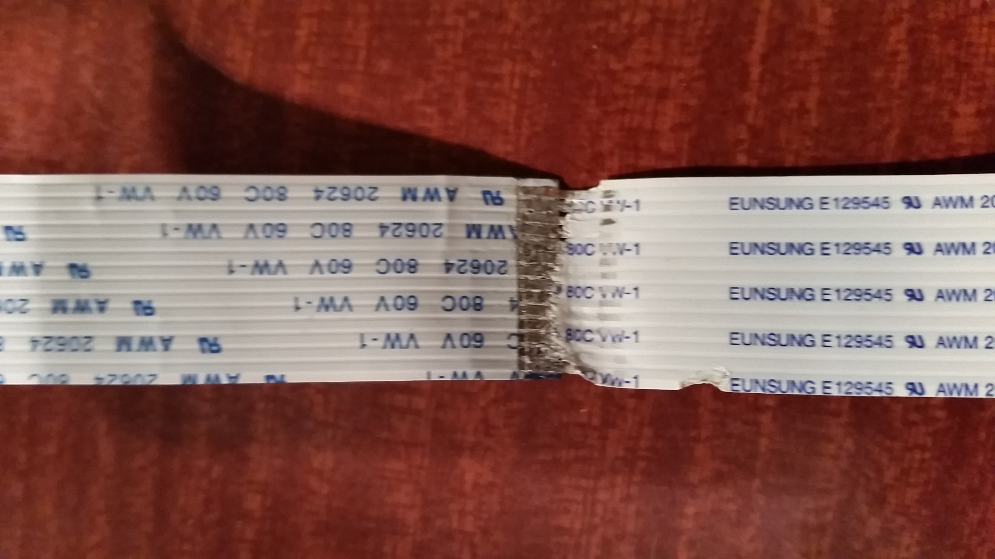
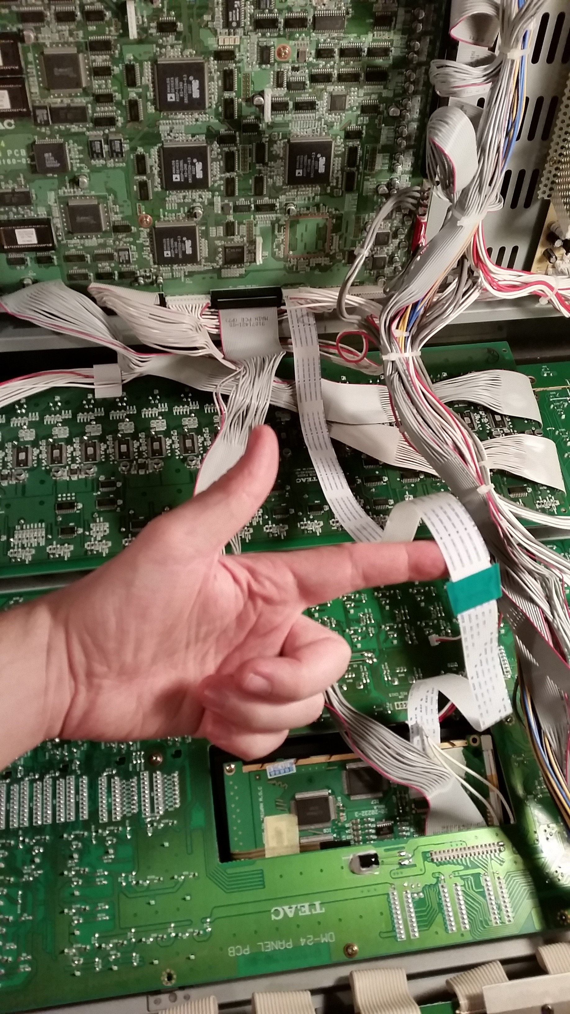
Problem #1 - the screen's flat data ribbon cable is way too short.
The cable on the new screen is soldered directly to the PCB. The cable on the old screen is detachable at both ends. A simple solution comes to mind; I just need to attach the old cable to the end of the new, to get a combined cable which is even longer than the original. That would certainly facilitate having to test the screen with it hanging outside the front of the mixer.
This proved to be way more tricky than you might think. The contacts on the ends of the cables are basically just thin metal foil, and it also seems that solder does not readily take to it. In trying to do so, the plastic ribbon starts to melt and burn. In the melting process the plastic also contracts, meaning that the metal contacts get closer together.
I tried several ways to strip back the plastic; scalpel, burning, fine metal file. During the course of these trials, I ended up losing about 30mm off the end of the old cable as I had to cut off the failed attempts to expose the contacts.
The best success came from using the file to wear away the plastic and expose the metal foil contacts. However, this did leave plastic ribbon in place between the contacts which would later cause a bit of an issue due to shrinkage and soldering surface contamination.
I ended up getting the contact surfaces tinned, but a bit heavy handedly. Upon trying to solder the contact pairs together, the surplus solder was squeezed out and shorted many of them together. Also, mixing with the surplus plastic, the contacts got closer together and mis-aligned, causing most of the contacts to be shorted together. I knew this by testing with a multimeter, and then by inspection under a microscope.
I made a better graft by using solder wick to remove the excess solder, and then repeating the soldering process under the microscope with soldering iron in one hand and the scalpel in the other to push, pull and hold each individual contact in the required location. In this process I also used the scalpel to scrape away the excess melted plastic and other surface contamination.
Finally, the ribbon cable was grafted, and tested OK, and I wrapped it all up with some electrical tape.
Testing the new screen
Problem #2 - the screen's display contrast
With a data cable that is long enough, I lashed up the screen and powered up the mixer. At this point I hadn't considered hooking up the back-light power, more on that later.
When powered on, even without back-lighting, it was obvious the screen was lacking contrast. It looks like I would have to examine the resistors on the PCB and attempt a modification there.
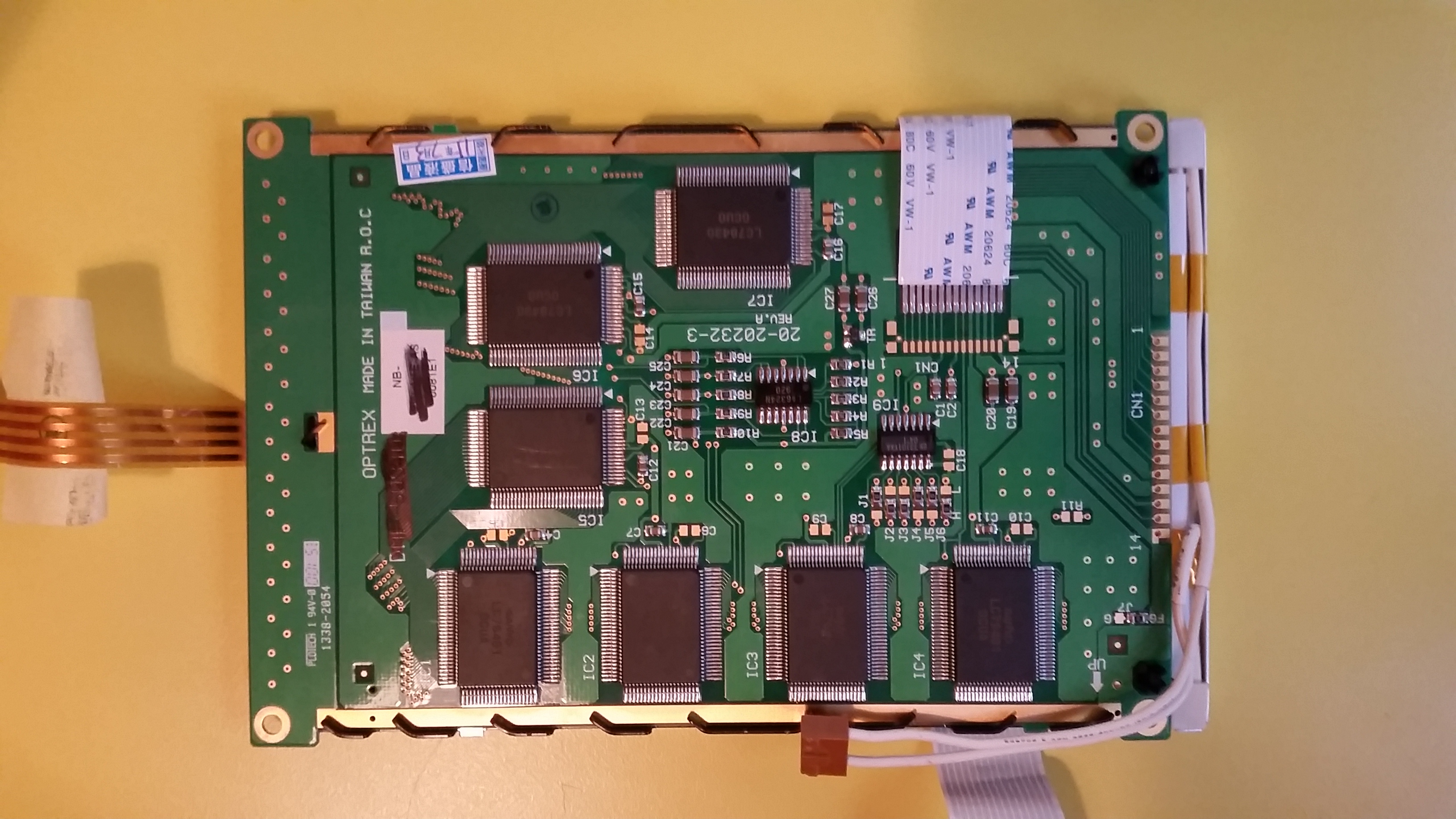
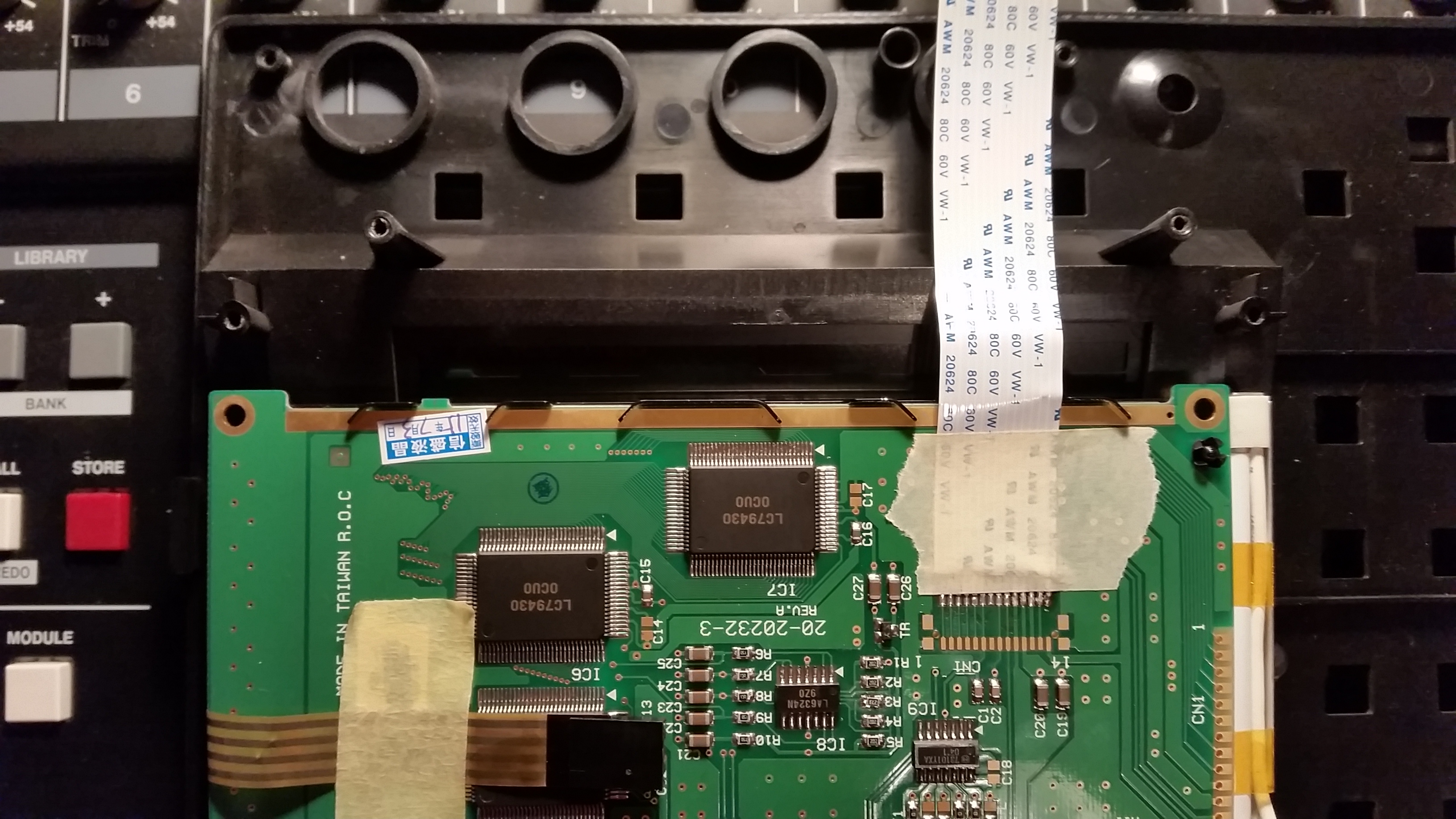
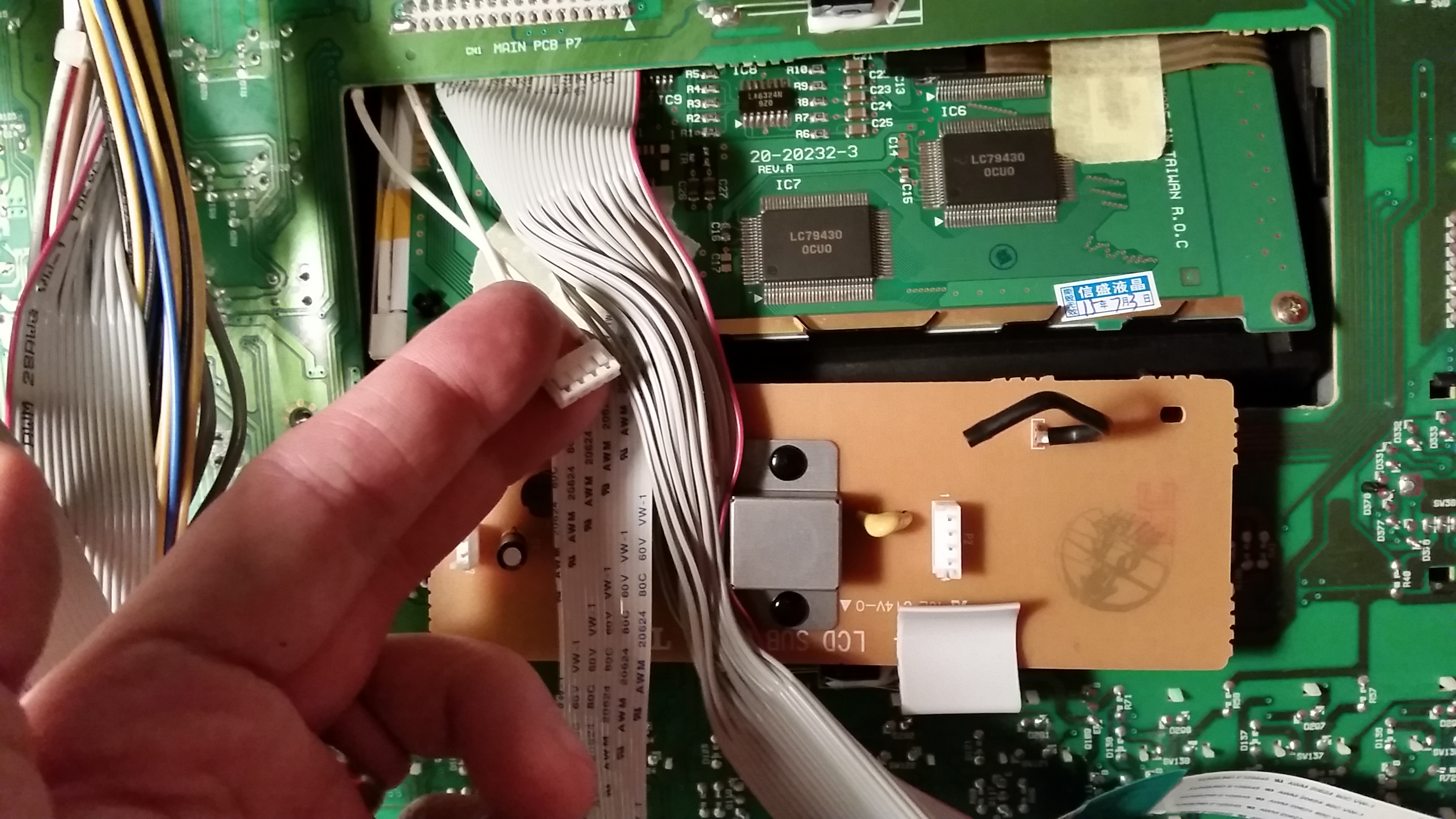
I removed the new screen and sat down to compare the components on the back of the PCB with the old one. I was trying to figure out the similarities and differences, and whether I would need to replace the "R3" resistor - or indeed, if the resistors marked "R3" on each board even perform the same function.
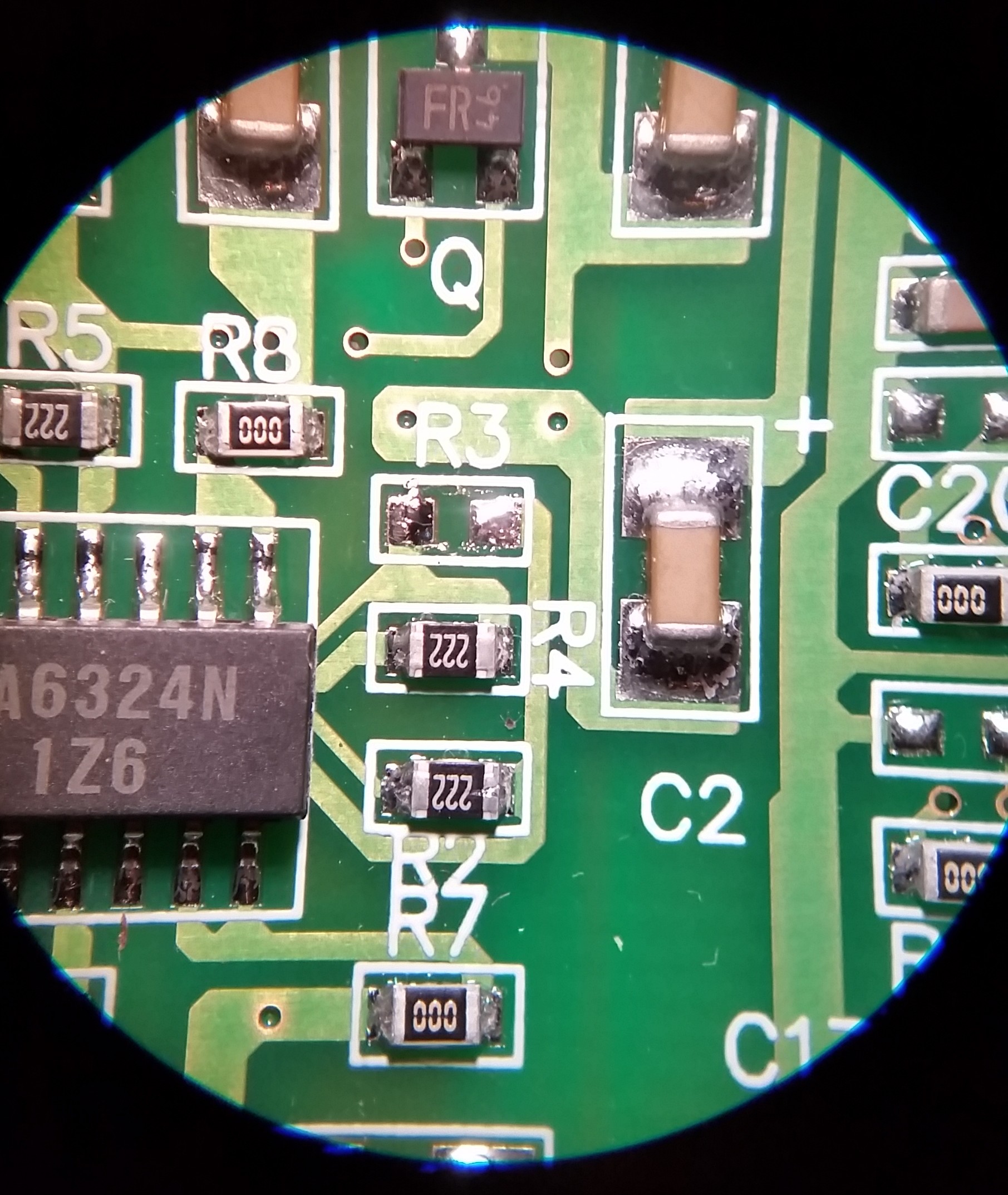
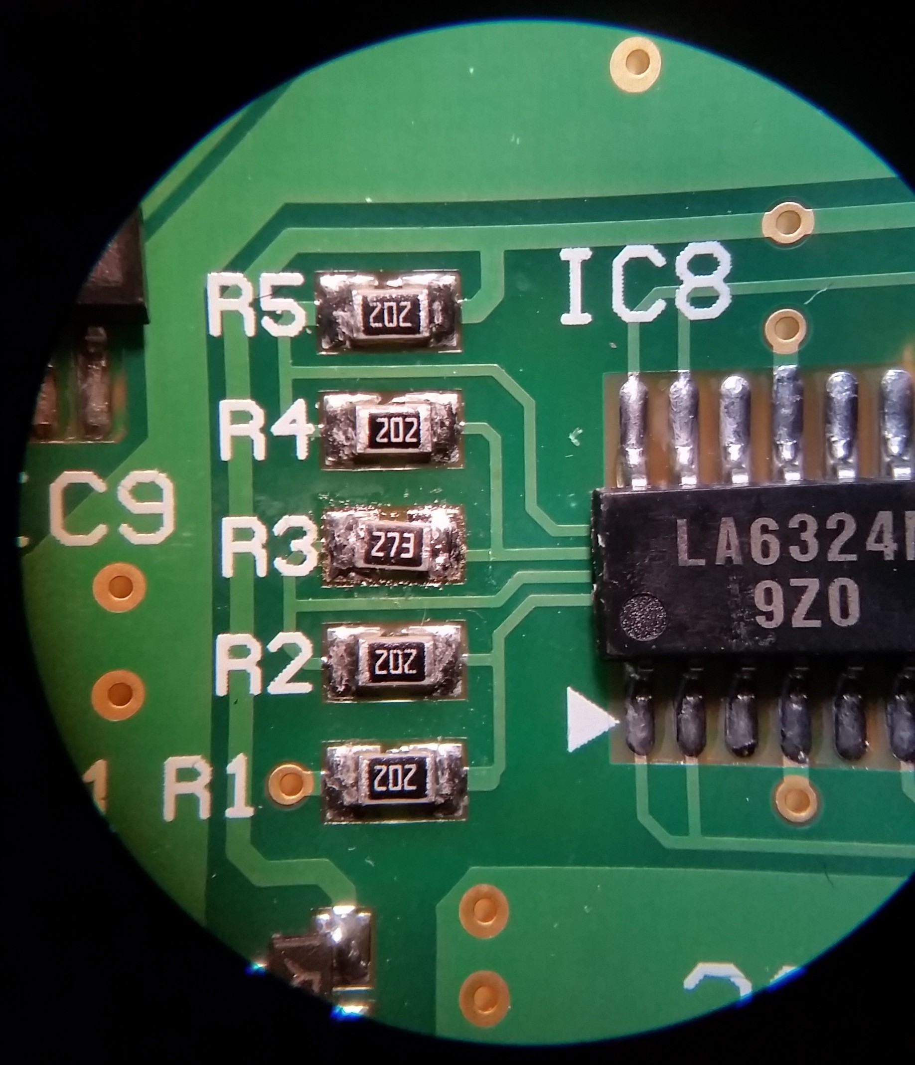
Here's the table of resistor values surrounding the "LA6324N" chip:
| Resistor Number | Old screen value | New screen value |
|---|---|---|
| R1 | 2k2 (222) | 2k (202) |
| R2 | 2k2 (222) | 2k (202) |
| R3 | 27k (273) | 20k (203) |
| R4 | 2k2 (222) | 2k (202) |
| R5 | 2k2 (222) | 2k (202) |
| R6 | 0 (000) | 15 (150) |
| R7 | 0 (000) | 15 (150) |
| R8 | 0 (000) | 15 (150) |
| R9 | 0 (000) | 15 (150) |
It seems like we're in luck. The numbering is consistent! The resistors with the same number have similar values on both screens.
Again soldering under the microscope I removed the R3 from the old PCB and the new, then soldered in the old 273 R3 onto the new board.
This leaves me with the old screen missing a resistor, and a spare 202 SMD resistor. Both of these will likely end up in the bin at some point.
The back-light power
Next step was to test the back-light. I quickly discovered that the new screen had the wrong type of molex connector fitted. Never mind, using a small blade I could remove the pins from the connector housing and swap them over.
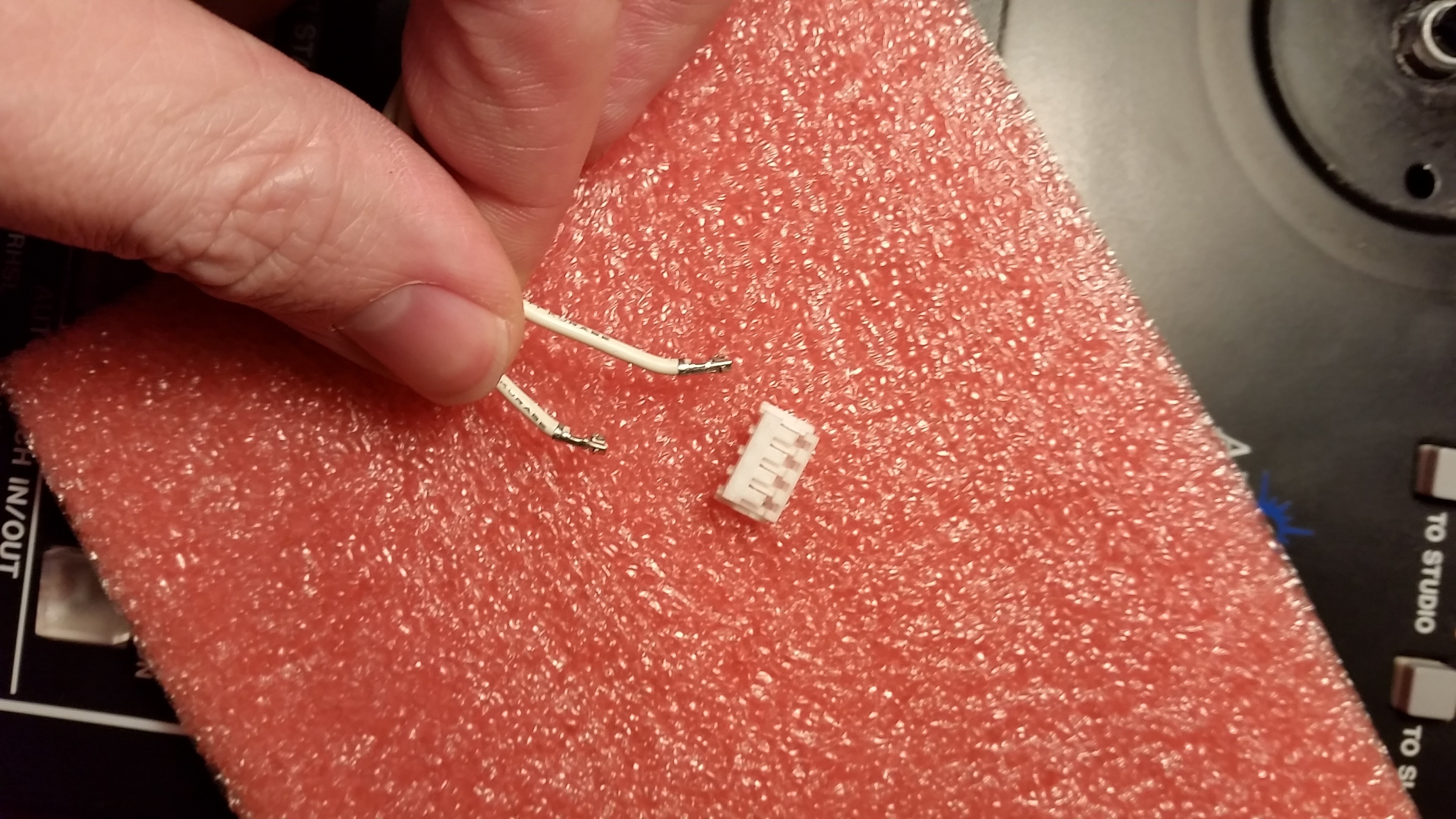
Unfortunately the crimped pin "sockets" on the new screen are of a slightly larger type and kept falling out of the connector casing, but when plugged in they would actually hold.
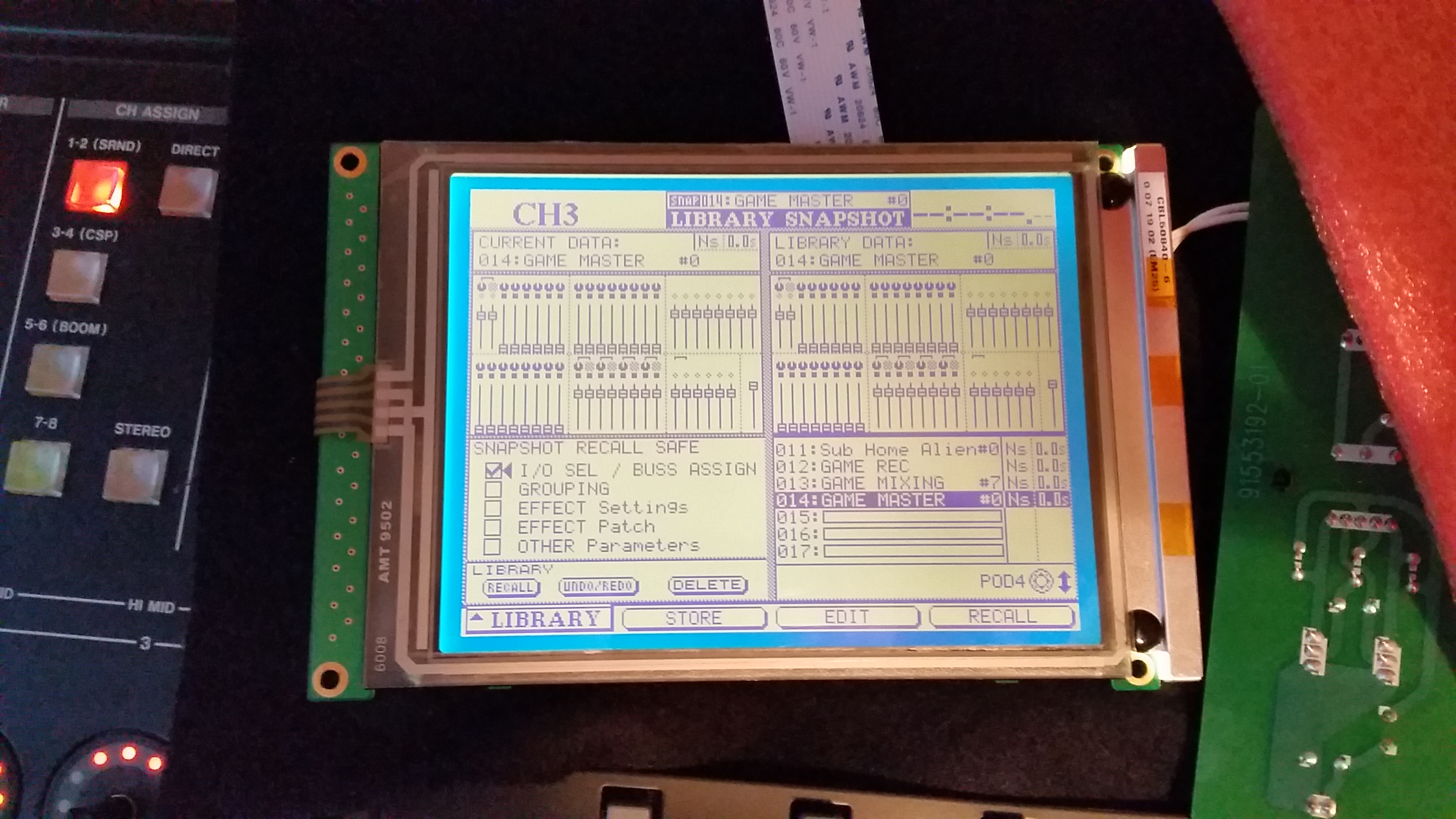
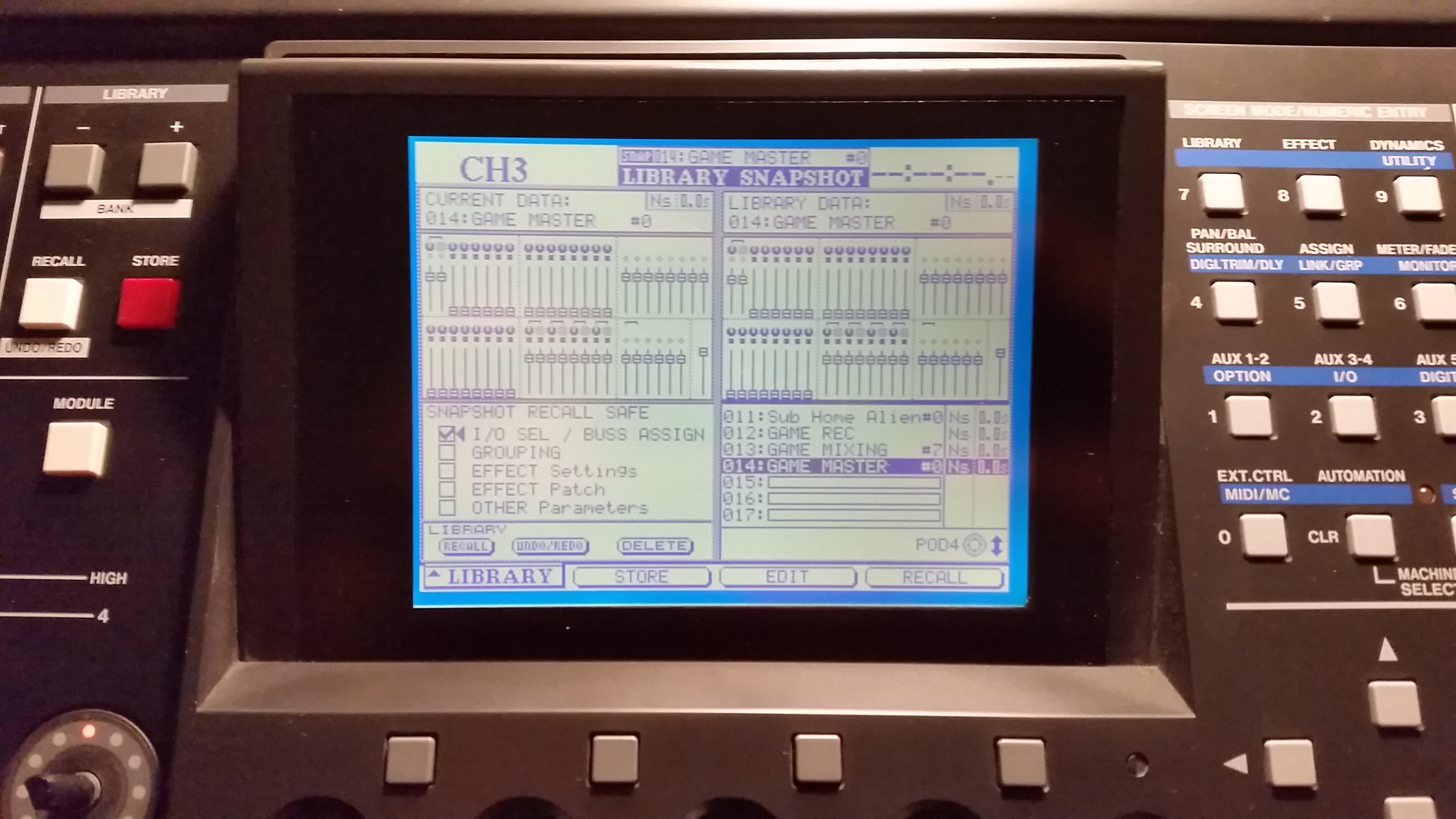
Testing the screen again
This time on power up the screen looks perfect, and the back-light works great.
Re-assembly
Happy that the screen will function, all I need to do now is get the thing fitted back in to the casing and put the mixer back together.
Oh dear. The mounting holes are in the wrong place. Not only that, but it doesn't seem to fit in the screen housing either.
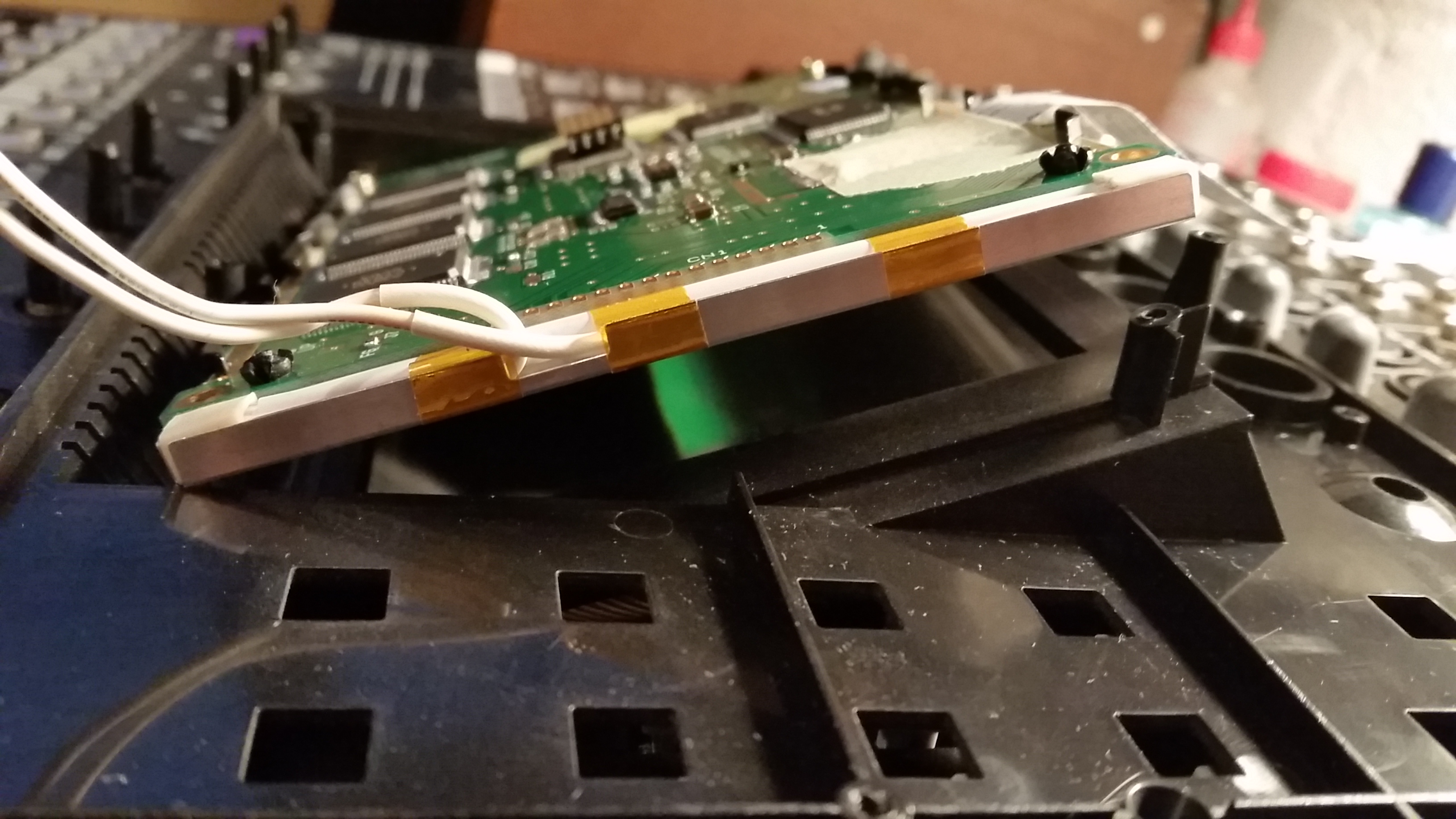
However, by putting in the two screws that I can, and picking up the assembly, the slight flex in the plastic actually let the screen drop in almost all the way in. There is no way that I can get the other two screws in. However, despite the fact that the screen is not quite flat, the appearance from the outside is actually completely acceptable.
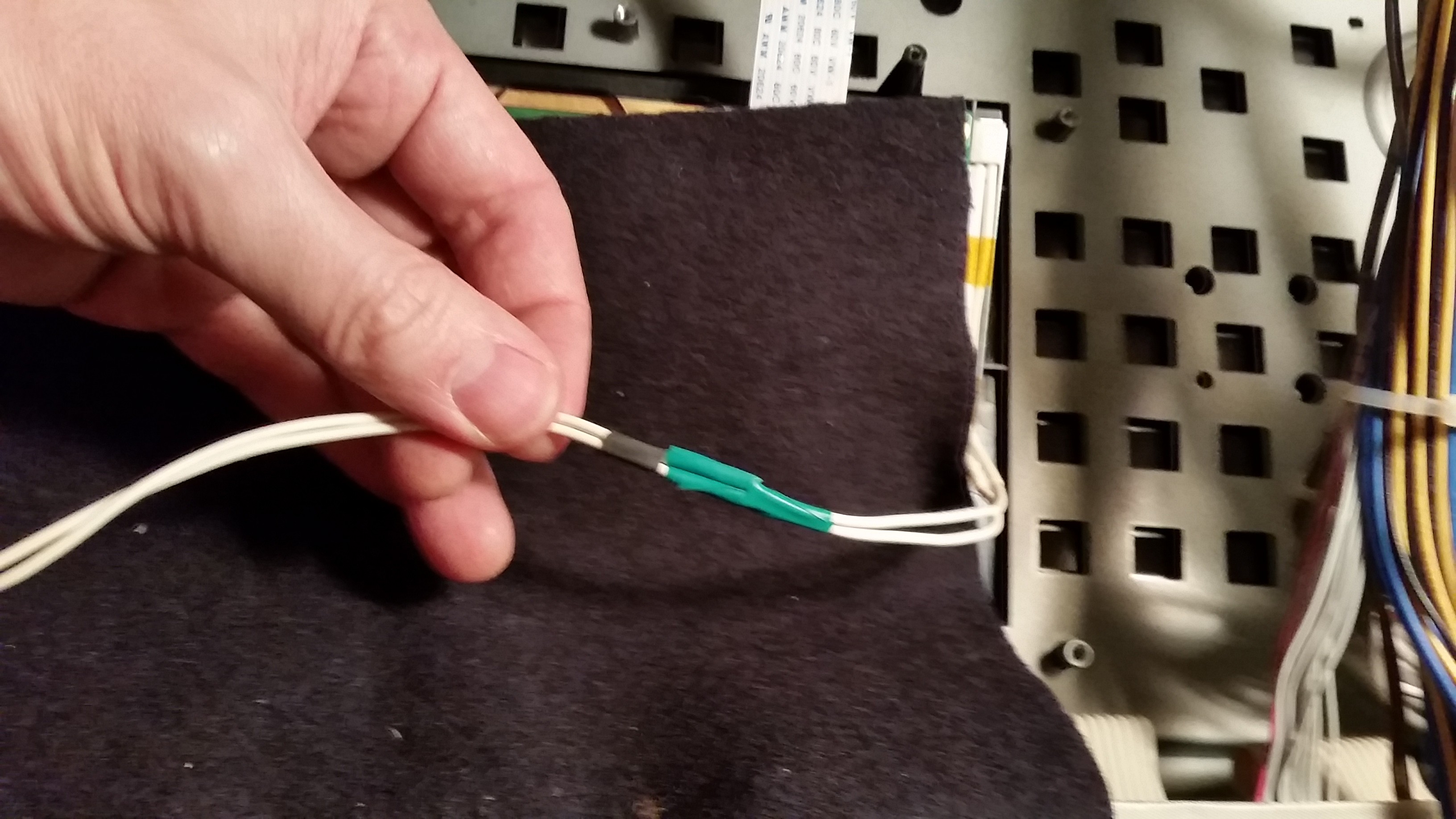
Next problem - the damn back-light power wires are way too short.
OK, easy solution here. I'll cut the wires off the old screen. This way I can extend the wires and use the original connector assembly. A quick graft later;
30 or so screws later and the mixer is closed up and back in a nice working state. The repair is not perfect, but it's good enough for me. No doubt the repair will last long enough - until either this LCD fails again or something else does.
:)