Interrupt driven LCD buttons
What do I mean by 'interrupt driven' ?
By design, the LCD board I have provides the state of the buttons to the application only when the application asks for it. This means that the application has to run a loop which continually asks the LCD board for which buttons are pressed. In an interrupt-driven world, the application will sit idle until a button is pressed, and then the LCD board will tell the application what has happened.
An analogy might be wanting to know when a particular time of day occurs. You could ring up the talking clock service every minute to check yourself. Or, you could set an alarm clock and let it tell you when it's the time you require, making you free to do other things in the mean time.
Why would I want 'interrupt driven' ?
It should be pretty clear already that having the application continuously polling the button state is wasteful of resources. Not only does it take up quite a bit of CPU time for the software, but it also occupies a significant portion of the available bandwidth on the i2c bus between the RPi and the LCD board. This is a problem for my project, since I also want to share that bus with one or more other devices which are more important than the LCD board and which also need to operate in (near to) real-time.
How did I make it work ?
The LCD board uses an i2c GPIO expander chip (an MCP23017) to interface between the RPi and the LCD itself. The buttons are set up as GPIO inputs on the expander chip. The board has been designed this way to minimise the number of connections required to the RPi. The MCP23017 actually has an interrupt facility for the GPIO inputs but due to the connections constraint they are not used. However, there's nothing stopping us hooking it up. The MCP23017 can be configured to raise an interrupt pin high when any of its GPIO inputs change. By connecting this signal to an RPi GPIO, we can detect when a button has been pressed.
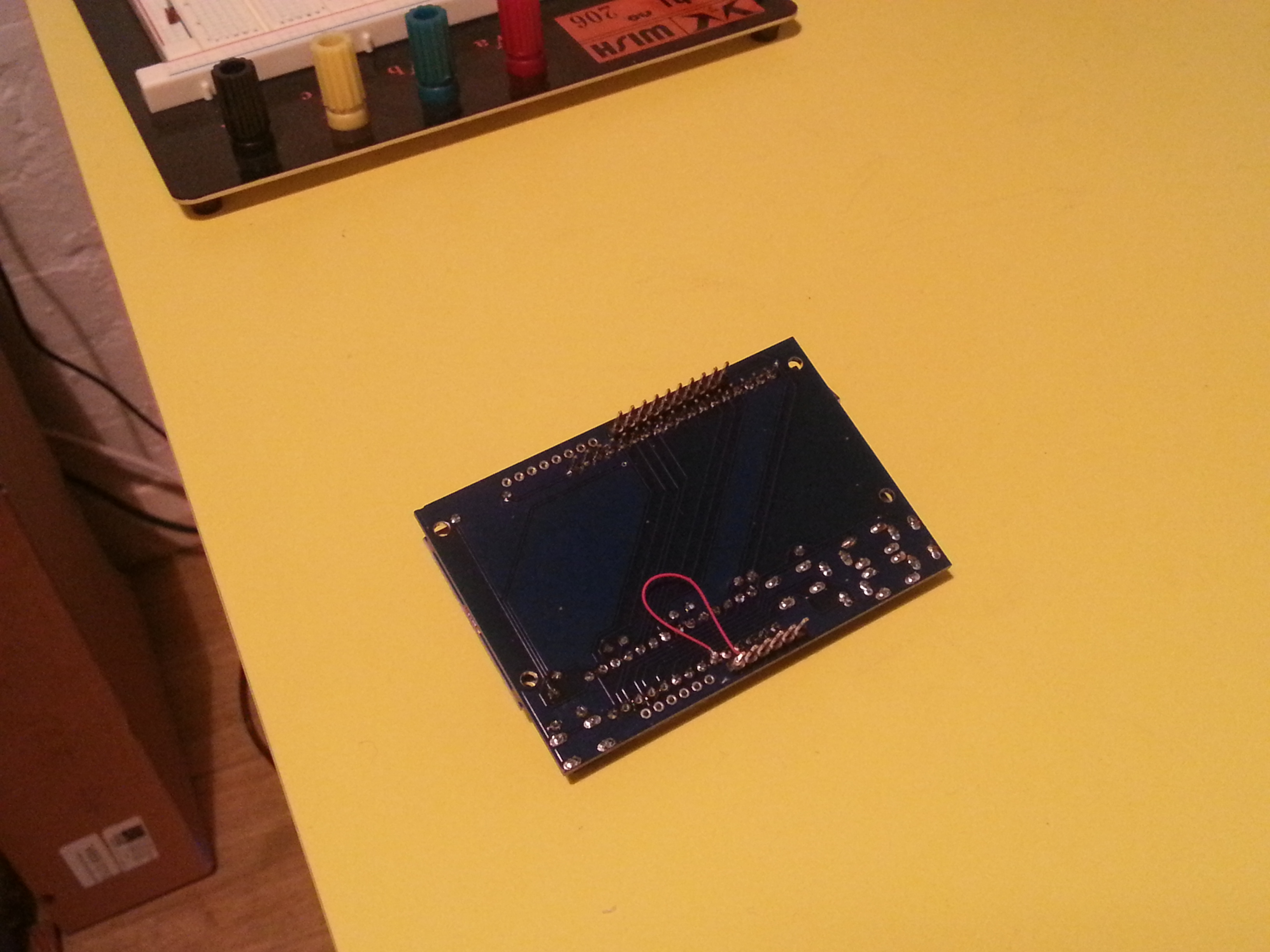
In the above picture, I have connected the INTA pin from the MCP23017 to one of the plate's unused pins; note that this pin I'm using was chosen simply as being the closest to the INTA pin, no other reason. It also makes this plate pin-incompatible with the Arduino it was designed for, but that's fine by me since I plug it into a breadboard anyway:
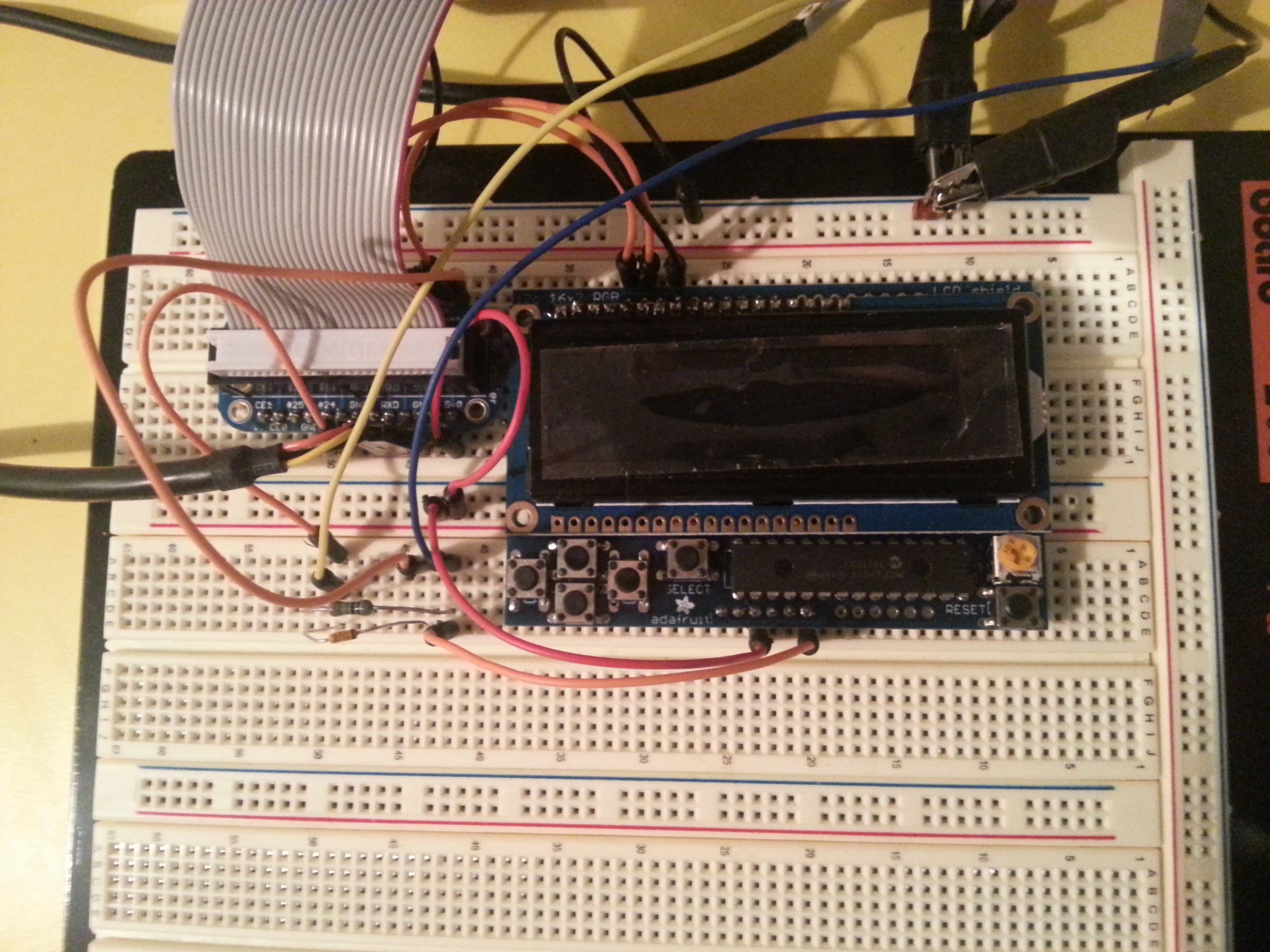
Here's the complete hookup on the breadboard with the Pi cobbler cable going to to the RPi. I've connected the INTA pin through a small circuit described here which limits the 5V MCP23017 output to something safe for the RPi's 3V3 GPIO inputs. Here, I am using GPIO23. You can also see the i2c lines in orange at the top, as well as the red/black 5V supply. The blue and yellow wires are hooked up to my oscilloscope so that I can check the GPIO voltages on the interrupt line.
Now, even though I am claiming the buttons are now interrupt driven, this still isn't strictly true unfortunately. I still have to keep asking the GPIO interrupt signal if it is high, and then ask the MCP23017 why the interrupt was raised. So why did I bother? The RPi can read the interrupt signal from the GPIO pin much faster than it can read the button states from the MCP23017 over i2c. This means that I save i2c bandwidth for my DAC device(s).
Below is the code which I use to poll the GPIO interrupt signal and turn it into qt signals:
	/**
	 * @brief pollInterrupt; poll the GPIO pin to see if it is high
	 * meaning that there is button information to be read from the
	 * MCP23017
	 */
	void pollInterrupt() {
		int btnIntr = m_pGPIO->digitalRead();

		if (btnIntr > 0) {
			readInterrupt();
		}
	}

	/**
	 * @brief readInterrupt; read the button interrupt registers from
	 * the MCP23017 and emit appropriate button down/up signals
	 */
	void readInterrupt() {
		uint8_t _in[] = { 0x00, 0x00 };
		m_pI2C->receive(MCP23017::INTFA, _in, 1);
		_logI2CFail();

		m_pI2C->receive(MCP23017::INTCAPA, _in + 1, 1);
		_logI2CFail();

		// work out what changed
		// INTFA is the address of the button which caused the interrupt
		// INTCAPA is the bitmask of currently pressed buttons;
		// therefore logical AND of these two tells us the current state
		// of the button which caused the interrupt.

		if (_in[0] & _in[1]) {
			// button down event
			emit buttonDown(_in[0]);
		} else if (_in[0] != 0) {
			// button up event
			emit buttonUp(_in[0]);
		}
	}
I also had to change the initialisation code to set up the MCP23017. The data sheet explained how to enable the INTA pin for the button inputs. Here is the new code:
	// Brute force reload ALL registers to known state.  This also
	// sets up all the input pins, pull-ups, etc. for the Pi Plate.
	uint8_t _registerInit[] = {
		0x3F,    // IODIRA    R+G LEDs=outputs, buttons=inputs
		m_ddrb,  // IODIRB    LCD D7=input, Blue LED=output
		0x3F,    // IPOLA     Invert polarity on button inputs
		0x00,    // IPOLB
		0x3F,    // GPINTENA  interrupt-on-change
		0x00,    // GPINTENB
		0x00,    // DEFVALA
		0x00,    // DEFVALB
		0x00,    // INTCONA
		0x00,    // INTCONB
		0x02,    // IOCON     BANK, MIRROR, SEQOP, DISSLW, HAEN, ODR, INTPOL, -
		0x02,    // IOCON
		0x3F,    // GPPUA     Enable pull-ups on buttons
		0x00,    // GPPUB
		0x00,    // INTFA
		0x00,    // INTFB
		0x00,    // INTCAPA
		0x00,    // INTCAPB
		m_portA, // GPIOA    Initial states for GPIO ports
		m_portB, // GPIOB
		m_portA, // OLATA
		m_portB  // OLATB
	};
	m_pI2C->send(0x00, _registerInit, 22);
	_logI2CFail();

	// Switch to Bank 1 and disable sequential operation.
	// From this point forward, the register addresses do NOT match
	// the list immediately above.  Instead, use the constants defined
	// at the start of the class.  Also, the address register will no
	// longer increment automatically after this -- multi-byte
	// operations must be broken down into single-byte calls.
	m_pI2C->send(MCP23017::IOCON_BANK0, 0xA2); // Originally 0xA0
	_logI2CFail();