Louper
Building a live looping application
A journey in discovering complexity in a relatively simple software application.
I wanted to play around with a live looping pedal, but for no cost. So, what to do?
I tried some of the existing (Linux) loop recorder applications, and none of them really grabbed me as a delight to use. I had my own ideas and pre-conceptions about how it should work, maybe that got in the way of using existing software - so maybe I should just proceed to make my own?
Getting Started
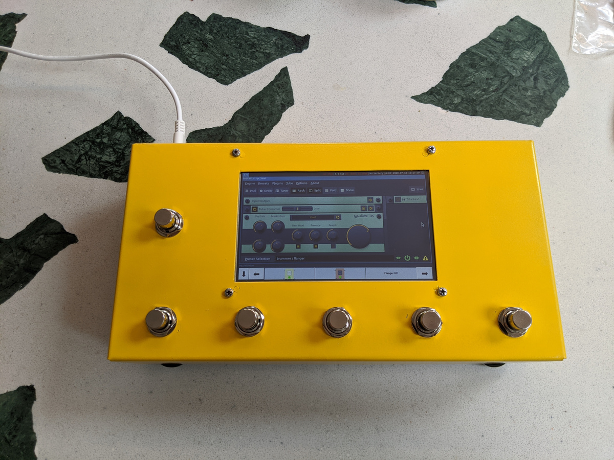
By building upon the platform I made for my Guitarix Pedal:
To be honest, I hadn’t really made much use of this pedal. I prefer analogue hardware for my guitar tones, and I had also perpetually put off the slightly tedious task of setting up my own presets for Guitarix.
But, underneath, it’s just a Raspberry Pi running Linux. I can run other applications on it, including my own.
Application UX Prototype
To get a grip on my ideas of how this would work, I made a mock-up of what I’d want to see on screen and what the footswitch buttons should do. In a spreadsheet.
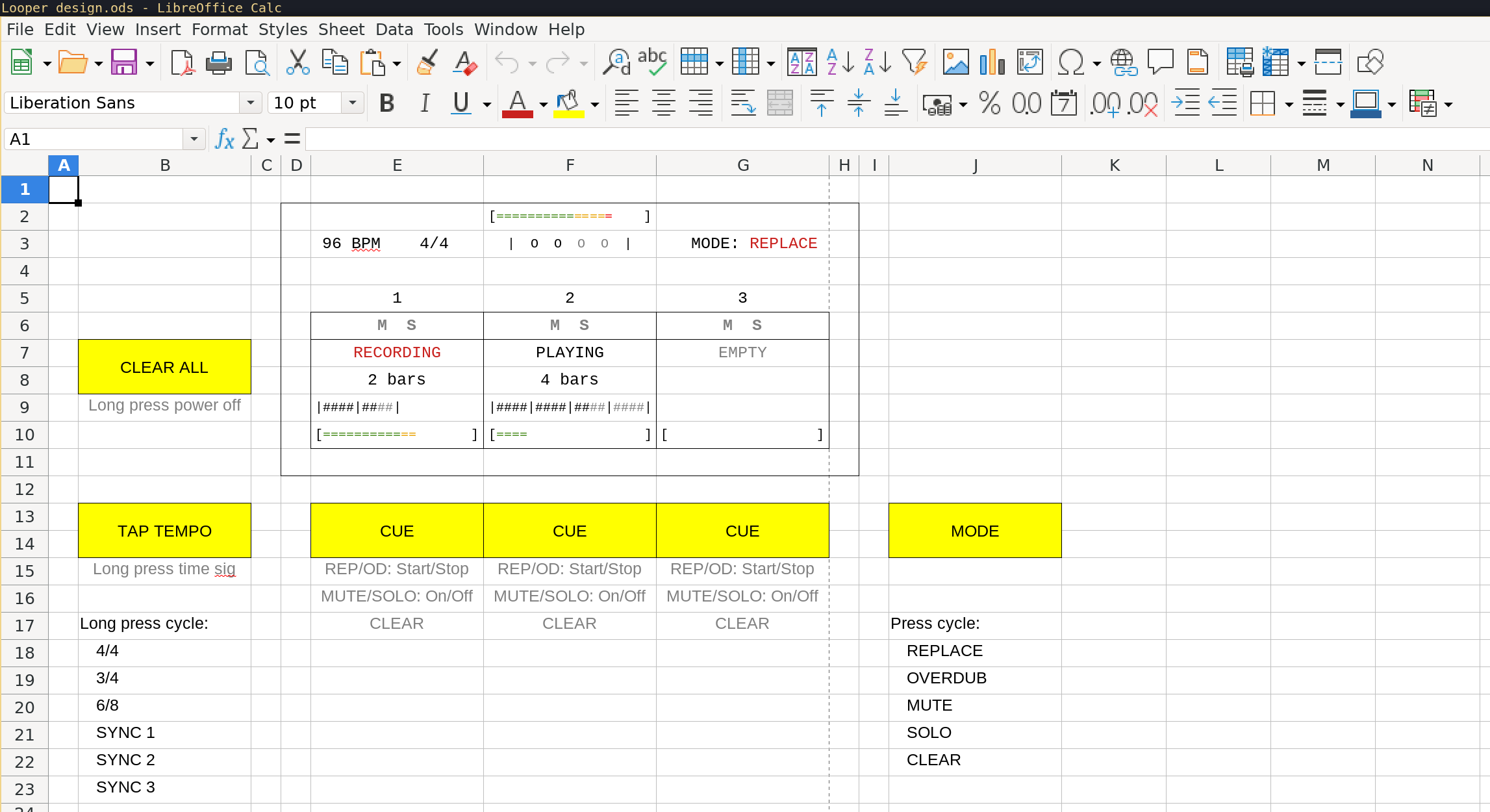
The screen shows the following components:
- Top: Output signal level meter
- Middle: Tempo & Time signature / Beat clock / Current mode
- Bottom: 3 loop recorder channels, each showing:
- Mute / Solo state
- Cue / Play state
- Loop length in bars
- Loop progress bar
- Loop audio play signal level
The 6 buttons in yellow are annotated with their primary function, secondary function and effects of those functions.
I also noted in the spreadsheet (not shown in the screenshot) some key behaviours and unanswered questions of the application. Some of these statements are inconsistent with the terminology on the mock-up, because I changed some of the terms during the application development. Not all of these requirements and questions have yet been addressed, but those that are are ticked here:
- Define “cycle” as end of current bar or end of longest loop?
- ✅ Every action happens at the end of the current cycle
- ✅ End of REC/OD immediately starts PLAY on next cycle
- Cannot record into 2 channels at once; last REC stops previous
- ✅ There are no channel input/output gain controls
- ✅ There is no master gain control
- Mono input
- ✅ Output 1: loops
- ✅ Output 2: click
- ✅ Click on pre-roll and first loop take only
- Configurable pre-roll?
- ✅ Loops extend in whole bar increments
- Change of tempo/sig/sync when 1 or more channels is not empty?
- Mute 1 channel == Solo 2 channels
- Solo 1 channel == Mute 2 channels
- There can be additional toggle buttons on screen, but not designed to be used mid-performance
But what do these specifications mean? How does this thing work?
Louper User Manual
The Beat Clock
There is a constantly running “beat clock” which ticks at the configured tempo and within the selected time signature. The current beat is shown prominently at the top of the display.
One of the footswitch buttons is dedicated to tempo and time control. Short press tap for tap-tempo to set the tempo. Long-press to cycle through the preset time signatures. (Actually, none of the long press functionality is working yet).
The first press of the Tap Tempo button will also start the Metronome, which emits a short beep on the monitor (left) output channel only on each beat. The Metronome is silenced once one of the Loop Recorders enters a PLAY state.
Loop Recorders
There are also 3x loop recorder channels, which operate synchronised to the clock, but in bar intervals.
All of the 3 recorders are attached to the same audio input.
Each recorder can be in one of several states:
-
CLEAR- contains no audio, the default state. -
REPLACE- when the recorder is recording new audio into its loop - the loop length increases in bar length increments. -
OVERDUB- when the recorder is recording new audio into its loop, but over the top of any existing recording - the loop length does not change. -
PLAY- when the recorder is playing out its recorded loop.
Once in a given state, the recorder will continue in that state unless told otherwise. However, the recorder can only change its state at the start/end of a bar - otherwise the application would require super-human timing to control.
To facilitate a smooth state change, each recorder also has a “cue” state. This cue state can be freely-selected at any time during a bar, but only becomes active at the end of the current bar. If there is no cued state, the loop recorder will continue on with its current state.
The state which will be used to “cue” a recorder is selected by pressing the “mode” button until the desired cue state is shown on screen, and then pressing the “cue” button for the desired loop recorder channel.
Generally speaking, the states are arranged such that a recorder can be “un-cued” by selecting the same cue state a 2nd time. For instance, to change your mind about entering REPLACE, you can select REPLACE again, and the recorder will not change state at the end of the bar.
You might also notice MUTE and SOLO “states” on the mode selector - these are actually not Loop Recorder states as such, they are actually Mixer states. As of today, this is implemented internally, and via the remote-control interface, but isn’t possible to select with the footswitches.
Other Internal Components
There also exists in the application a Metronome, as described above. This is fairly basic and emits short A-note beeps on the beat. There is also a Passthrough channel and an audio Mixer, so that the input can always be heard, and mixed with all the other channels before reaching the output.
The application is also running an OSC server for remote-control. The inputs from the hardware buttons are implemented as a separate process which sends messages to this server.
Make it stop!!!
There is a dedicated footswitch button to “clear all” of the loop recorders, to make the noise stop at the end of the current bar.
System Design
I wrote this application in C++ since we require maximum performance, to aim for low latency “real-time” audio processing. It’s a fairly standard cmake project outputting a library and several binaries.
There were some interesting challenges in getting the above to work though.
Loop Recorder States
It is probably apparent if you read the above “manual” that the Loop Recorder state control could easily get out of hand and not work correctly.
Each Loop Recorder actually implements two linked state machines.
The state machines are a little tricky to describe, given that the state names and events have the same names, and also that both machines also deal with the same states and events. Remember that the Loop Recorder “state” is what the recorder is currently doing. The “cue state” is what you want it to do next. The events describe what you want the “cue state” or “state” to change to now. Put another way, the “cue state” is used as an event for the next “state”.
This is made worse by me now describing State Machines to change two different “states”. Clear? OK, here’s the state machine definitions…
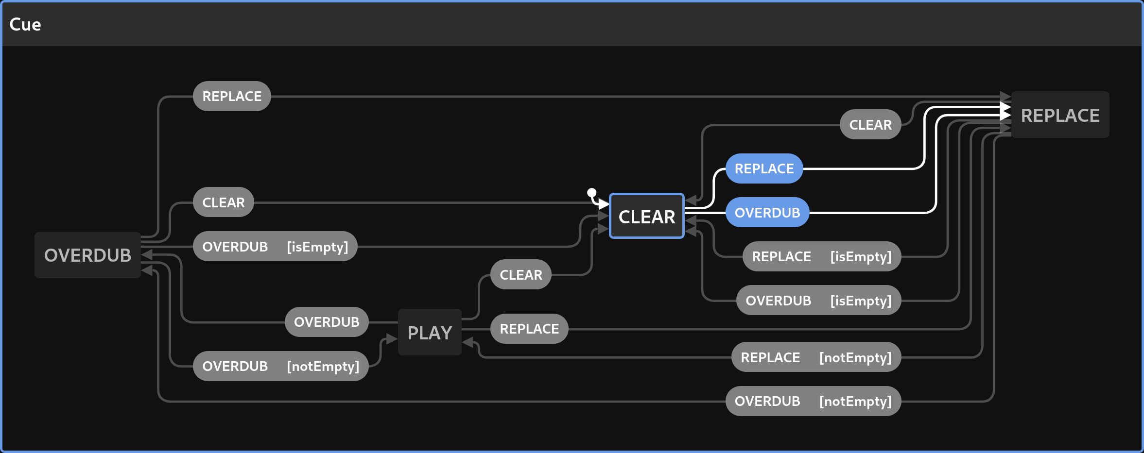
State Machine 1 - Cue State
This is an interesting machine to construct. I didn’t expect all these transitions and conditions when I started, but when playing with the state changes, it quickly emerges that this is required, just to make the behaviour feel intuitive and correct.
And unfortunately, I have to describe this monstrosity first, else the other state machine makes no sense.
- Cue States :
PLAY-REPLACE-OVERDUB-CLEAR - Events :
REPLACE-OVERDUB-CLEAR - Transitions :
- Cue State
PLAY+ EventREPLACE=> Cue StateREPLACE - Cue State
PLAY+ EventOVERDUB=> Cue StateOVERDUB -
Cue State
PLAY+ EventCLEAR=> Cue StateCLEAR - Cue State
REPLACE+ EventREPLACE- => Cue State
PLAYIF the recorder is not empty - => Cue State
CLEARIF the recorder is empty
- => Cue State
- Cue State
REPLACE+ EventOVERDUB- => Cue State
OVERDUBIF the recorder is not empty - => Cue State
CLEARIF the recorder is empty
- => Cue State
-
Cue State
REPLACE+ EventCLEAR=> Cue StateCLEAR - Cue State
OVERDUB+ EventREPLACE=> Cue StateREPLACE - Cue State
OVERDUB+ EventOVERDUB- => Cue State
PLAYIF the recorder is not empty - => Cue State
CLEARIF the recorder is empty
- => Cue State
-
Cue State
OVERDUB+ EventCLEAR=> Cue StateCLEAR - Cue State
CLEAR+ EventREPLACE=> Cue StateREPLACE - Cue State
CLEAR+ EventOVERDUB=> Cue StateREPLACE
- Cue State
You might notice that this can automatically cycle through many Cue States if you are inputting OVERDUB events and the recorder itself is already in a certain state; e.g. OVERDUB => REPLACE => CLEAR => REPLACE => …
This probably isn’t desirable and needs some testing and tweaking.
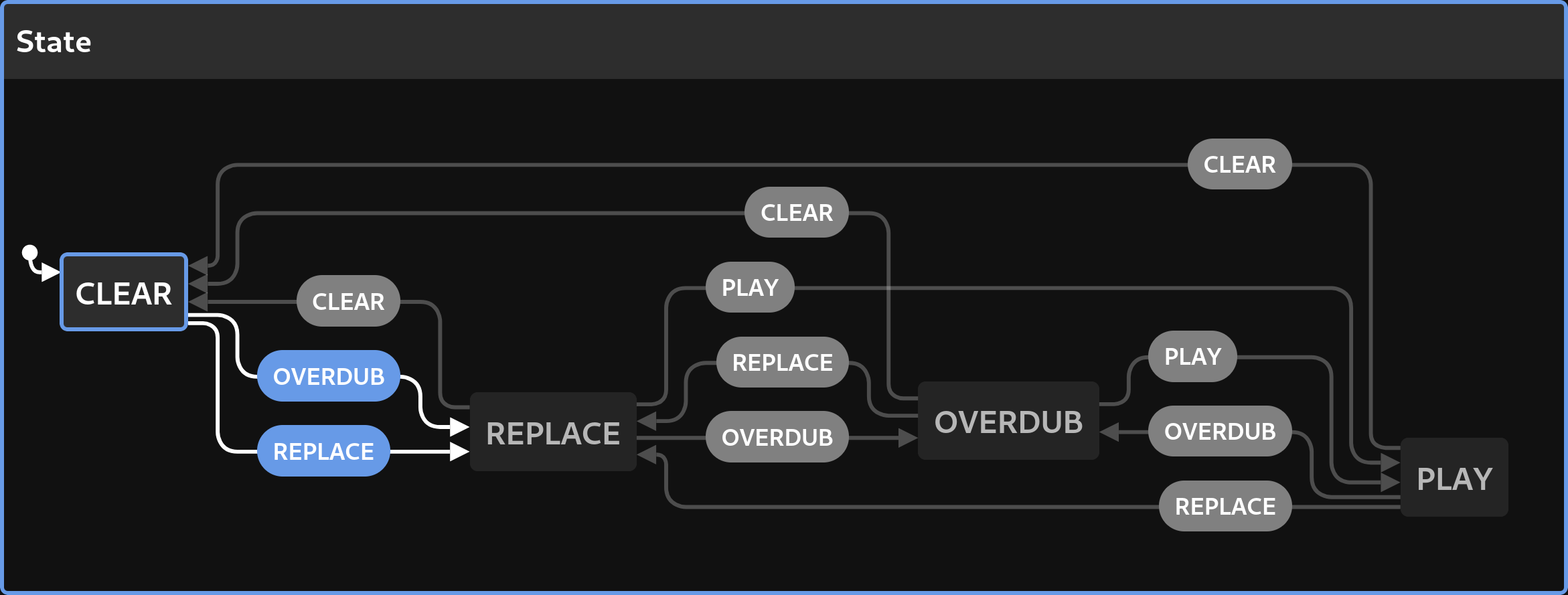
State Machine 2 - State
This one is a little more straightforward, it didn’t require any conditions.
- States :
PLAY-REPLACE-OVERDUB-CLEAR - Events :
PLAY-REPLACE-OVERDUB-CLEAR(These are actually “Cue States” !) - Transitions :
- State
PLAY+ Cue StateREPLACE=> StateREPLACE - State
PLAY+ Cue StateOVERDUB=> StateOVERDUB -
State
PLAY+ Cue StateCLEAR=> StateCLEAR - State
REPLACE+ Cue StatePLAY=> StatePLAY - State
REPLACE+ Cue StateOVERDUB=> StateOVERDUB -
State
REPLACE+ Cue StateCLEAR=> StateCLEAR - State
OVERDUB+ Cue StatePLAY=> StatePLAY - State
OVERDUB+ Cue StateREPLACE=> StateREPLACE -
State
OVERDUB+ Cue StateCLEAR=> StateCLEAR - State
CLEAR+ Cue StateREPLACE=> StateREPLACE - State
CLEAR+ Cue StateOVERDUB=> StateREPLACE
- State
All of this basically just describes basic tape recorder machine mechanics, that would be familiar to anyone who used or played with a real hardware tape recorder. e.g. “You cannot play if there’s no tape in the machine”, “Overdubbing onto an empty tape is the same as recording (replacing) on to it”.
Other Components
Most of the other components are nowhere near as complex as this, they are fairly boring and exist to support the Loop Recorders:
-
AudioDrv: Interfaces with the audio subsystem. I chose thertaudiolibrary to drive this, as it had a straightforward method of doing duplex audio. Once started, the library calls us back at regular intervals with input and output buffers. All we have to do is read the input, “perform some processing” and write back to the output buffer. -
Control: Starts an OSC server for remote control. The inputs from the footswitches are actually handled by an entirely different process, which sends messages to the main application via OSC. -
Meter: Derives peak and RMS values for audio signals. -
Mixer: Mixes multiple audio signals together. I’ll explain which signals below. -
TapTempo: Tap tempo calculator. Receives events and calculates the (average) duration between them as beats-per-minute. -
Transport: Derives bar and beat clock values from tempo, time signature, sample rate and buffer sizes. I may have lied about all of these components being simple. This one was not entirely straightforward either. - Other channel types:
-
Passthrough: Simply copies input to output, used to provide a monitor of the input, so you can hear what you’re playing. -
Metronome: Generates beeps on the beat, driven byTransport.
-
-
Looper: The main application controller which sets up and glues together all of the above.
At least two of these deserve a bit more explanation;
Mixer
Perhaps a block diagram of the audio signal flow might explain why we need this:
  [Audio Input] ----+---- [Loop Recorder 1] ----\
                    +---- [Loop Recorder 2] -----+
                    +---- [Loop Recorder 3] -----+[Mixer] ---- [Audio Output]
                    \---- [Passthrough] ---------+
                                                 |
                          [Metronome] ----------/
Whilst it is simple to provide all the channels with the same input buffer to process (they literally all read the same buffer in turn), in order to hear all the signals at once we must add up the values from their outputs to provide to the audio output. Hence, we mix them together.
Note that the Metronome doesn’t use the audio input, it generates its own signal.
Transport
Since we are wanting to operate in musical time increments of bars and beats, we need something which can tell us where we are in the music. This component exists to translate the running time of the application in to bars and beats values.
This became surprisingly tricky, given that the application is actually timed from the AudioDrv callbacks. The audio driver gives us a callback with buffers of fixed a length, which typically are a power of or multiple of two. The intervals between these callbacks depend on the sample rate and the buffer size we chose to work with when we started the system. Everything else in the application is synchronised to these callbacks.
For example, I found that the Raspberry Pi likes to operate reliably using a sample rate of 32000 samples per second and a buffer size of 96. We therefore get 1000 callbacks every 3 seconds. This happens regardless of the tempo we want to use, and never changes whilst the application is running.
Aside: it also determines our processing latency, which in this case is 3 milliseconds - low enough to use live and not notice - that also means that the all processing we do inside the callback must be completed within this time period.
What we want, however, is events to be fired inside the application exactly when a bar end or beat is occurring. e.g. to drive the Metronome, or to change the Loop Recorder channel states. These events almost never will happen in between audio callbacks, but most likely part way through, and never always in the same place. This also depends on the chosen tempo.
What the Transport does, is to count each callback and accumulate a total of the number of samples elapsed. It also knows how many samples long a bar and beat are, so for a given callback it can calculate the indices of the buffer at which these events should occur. This involves a nasty algorithm which I discovered via test-driven-development and haven’t really fully analysed yet. It has to deal with the fact that the bar or beat length may be less than, the same as or greater than the audio driver buffer length - it makes no assumptions. Therefore, in any given callback, there may be zero, one, or many indices at which these events occur.
During the audio callback, we can then emit events part way through the buffer processing for bar and beat at the indices given to us by Transport, thus ensuring every state change in the application is accurately timed according to the musical time.
GUI
Yes, I implemented GUI for this, using Dear ImGui:
Its designed to fit nicely on the pedal’s 800x480 screen and be readable from the floor. It could do with a couple of tweaks already, e.g. the time signature is not displayed.
The Code
The code is GPL 3 licensed and available on my bitbucket: doughammond/louper
Why “Louper” ?
For my wife, Louisa, I set this name on Valentine’s day 2022 ❤️