The Task Switch
What is this ?
I have built a little box of buttons which I can use to record the time I spend on each activity at work. Mostly just for my own amusement. I’ve open sourced the entire concept, software and physical designs (links at the bottom).
This blog post doesn’t really go into a lot of the gritty detail of the build of this project, unfortunately trying to achieve that might just take longer than the build already did. So, apologies if this skims over some of the interesting stuff, but you could always have a dig through the repos later.
Background & Motivation
We are all from time to time either curious about or get asked to record the time we spend on activities. There is a particularly long running practice of this at my work, and in fact I have for nearly 6 years now been working in a team which provides the company’s Time and Attendance solution (amongst other business tools). Because of this, I am very aware of the benefits of such practices, in that it allows you to use that data for several quite important purposes, for example:
- Figuring out the total cost of a project,
- Being able to more accurately estimate projects,
- Being able to report and push back on activities which are a “waste of time” or “not what I should be doing”.
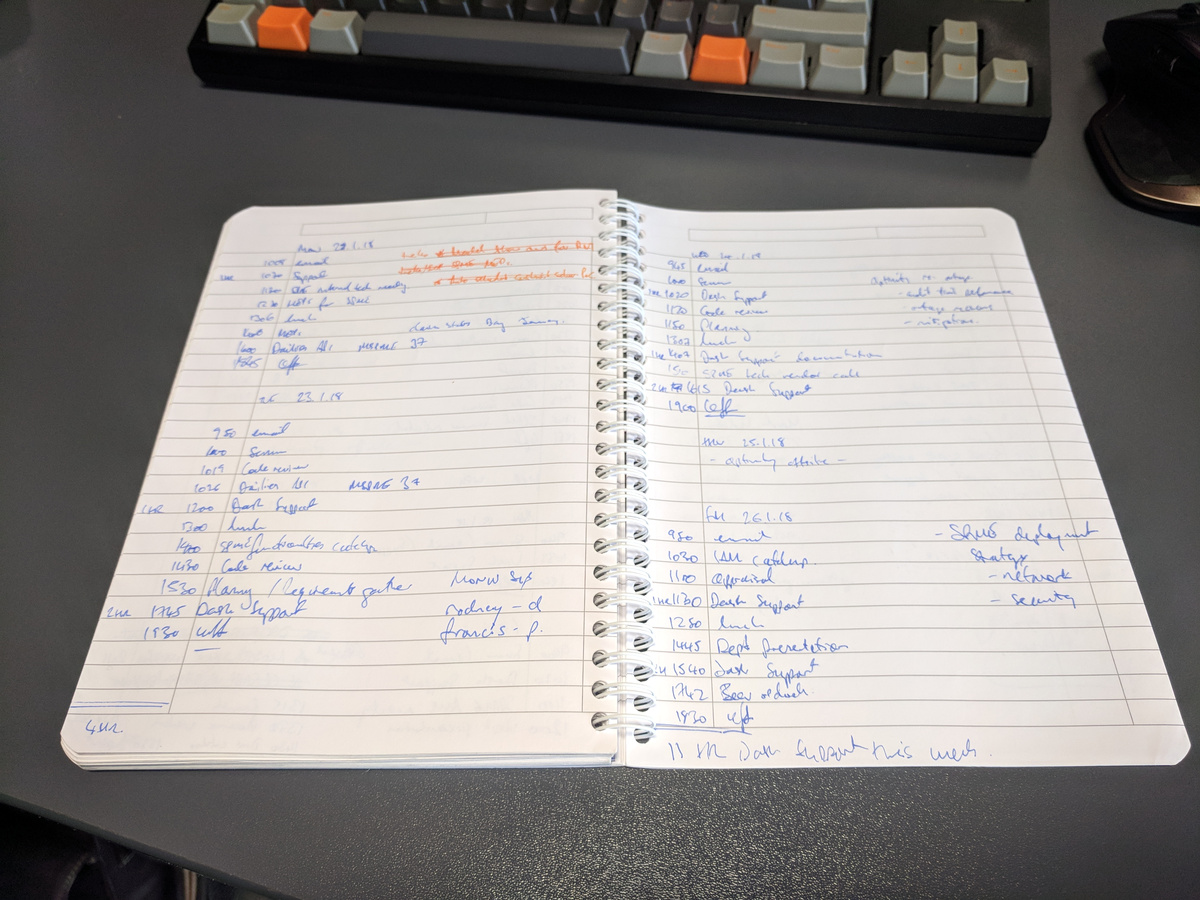
I first started recording my distractions using a notebook and pen, as at that time there was quite a few happening and management wanted to know why our team was always going over our estimates. My opinion was that we were being badly managed, and that there was some difference of expectations of what each other should be doing. That all eventually got resolved, but the practice of habitually recording all of my activity remained with me.
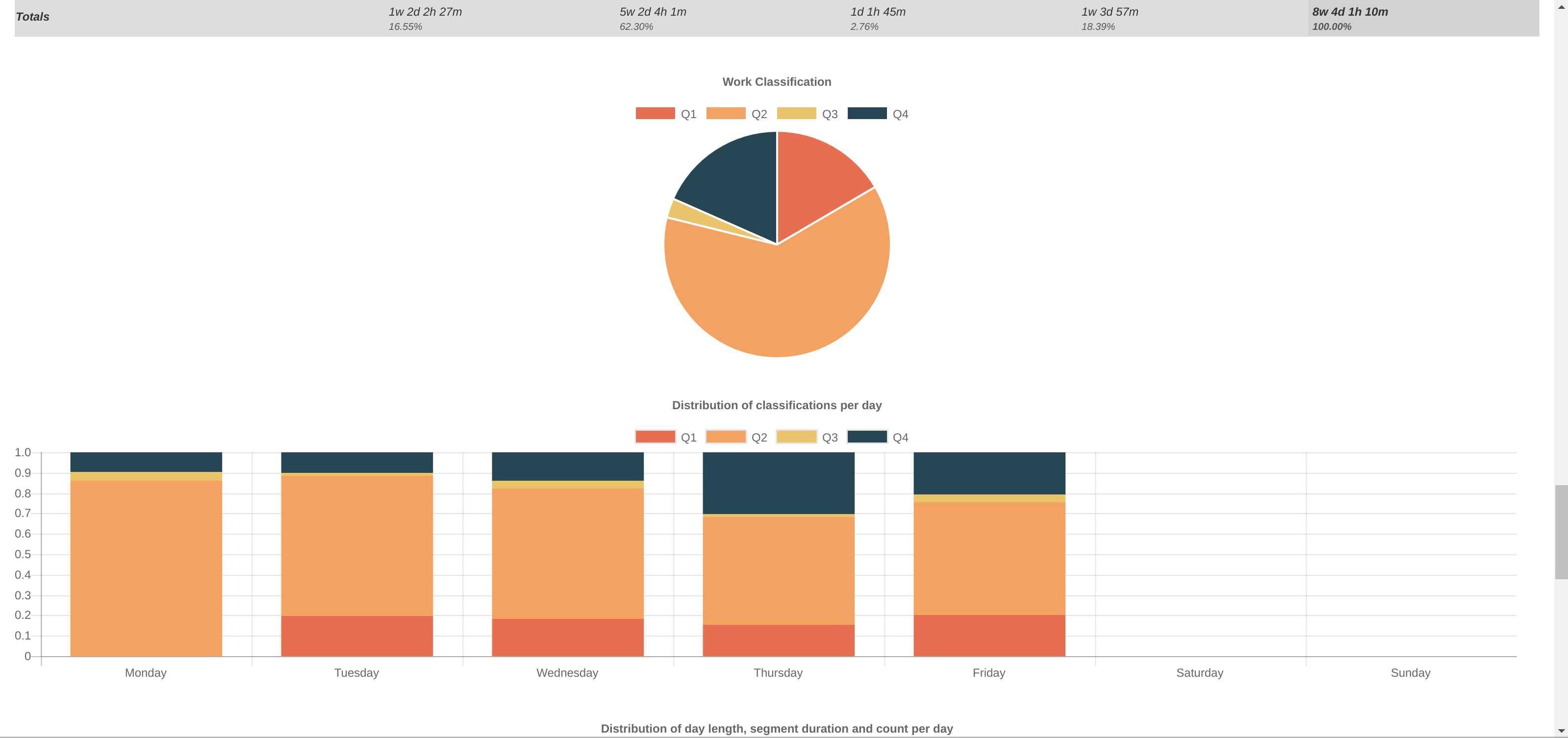
Naturally as part of that process I needed to analyse the data I recorded. This started off using Excel sheets; I copied the notebook entries into the sheet, and started to classify each item according to importance/urgency (see The Eisenhower Method). In this step I could also calculate the duration of each activity. The end result being a nice pie chart per week of time spent in each “Quadrant”. Looking at this data, I could then try to establish how to spend more time in “Q2” and less in the others. Mostly by the reduction in interruptions and distractions.
Of course, doing all of this by hand was very time consuming. It could take 60 to 90 minutes at the end of each week to input all the data. Also, wrangling numbers in the same way in a repeated and consistent fashion in Excel is extremely laborious. I eventually wrote a little web app which could ingest the data in YAML format and do the calculation and presentation for me. However, I still had to type out the YAML data by hand.
Eventually I stopped putting the data into the computer as the work situation improved significantly, but I still kept the habit of writing activities down in a notebook. I found in fact the act of writing down each context-change a useful mental tool, to ensure I stayed on the task at hand and did not wander off doing something else.
Just over a year passed of notebook logging, and then it struck me that I would like to perform the reporting again, but mostly out of curiosity than necessity. Unfortunately the year’s worth of hand written notes is not going to get typed into the system, I will have a big gap in my data.
Initial concept
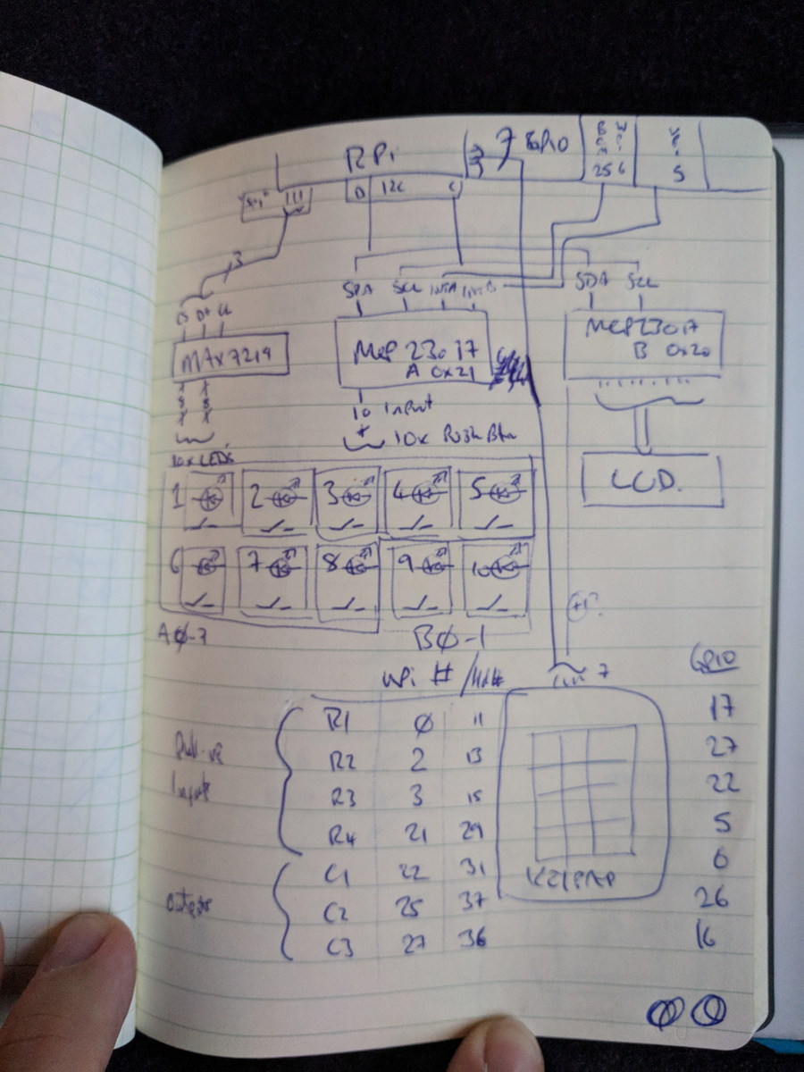
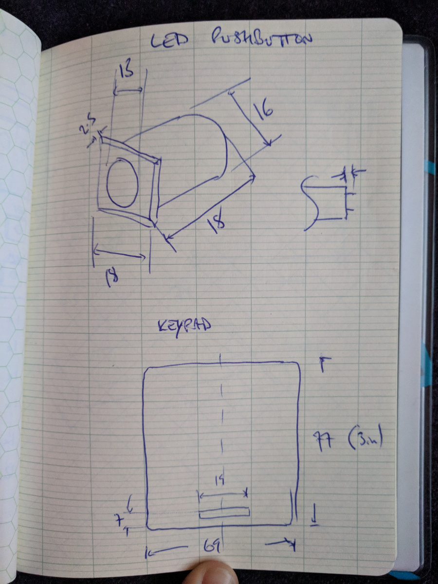
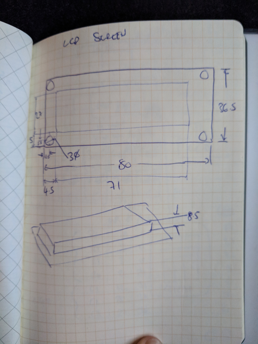
On 4th March 2018, near the end of an idle Sunday at home, almost out of nowhere, I sketched the first concept for the design of something I wanted to build.
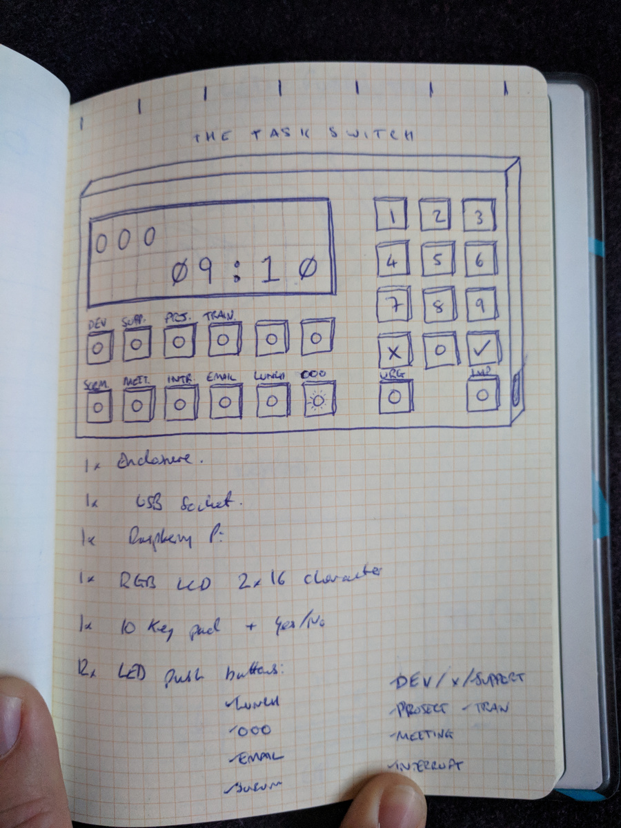
I realised that I wanted a way to input quickly into a computer my current activity and I eventually realised that in fact it does not need to be incredibly detailed. All I need to be able to do is record enough information to derive an Eisenhower Quadrant number and a duration for each activity.
My number one UX requirement is that the input should be as quick, or quicker than writing a few words with a pen.
This would also generally require that the activity logger should not be running on my main workstation. My workstation is a protected environment where the act of recording a context-switch is in itself too much of a context-switch. Add to that the constraint that our workplace workstations have no internet access and is extremely difficult to install and run arbitrary software and I quickly came to the former conclusion. The final justification for this solution is that I am not always at my desk during a context-switch (e.g. back to back meetings), then something separate and potentially portable makes sense.
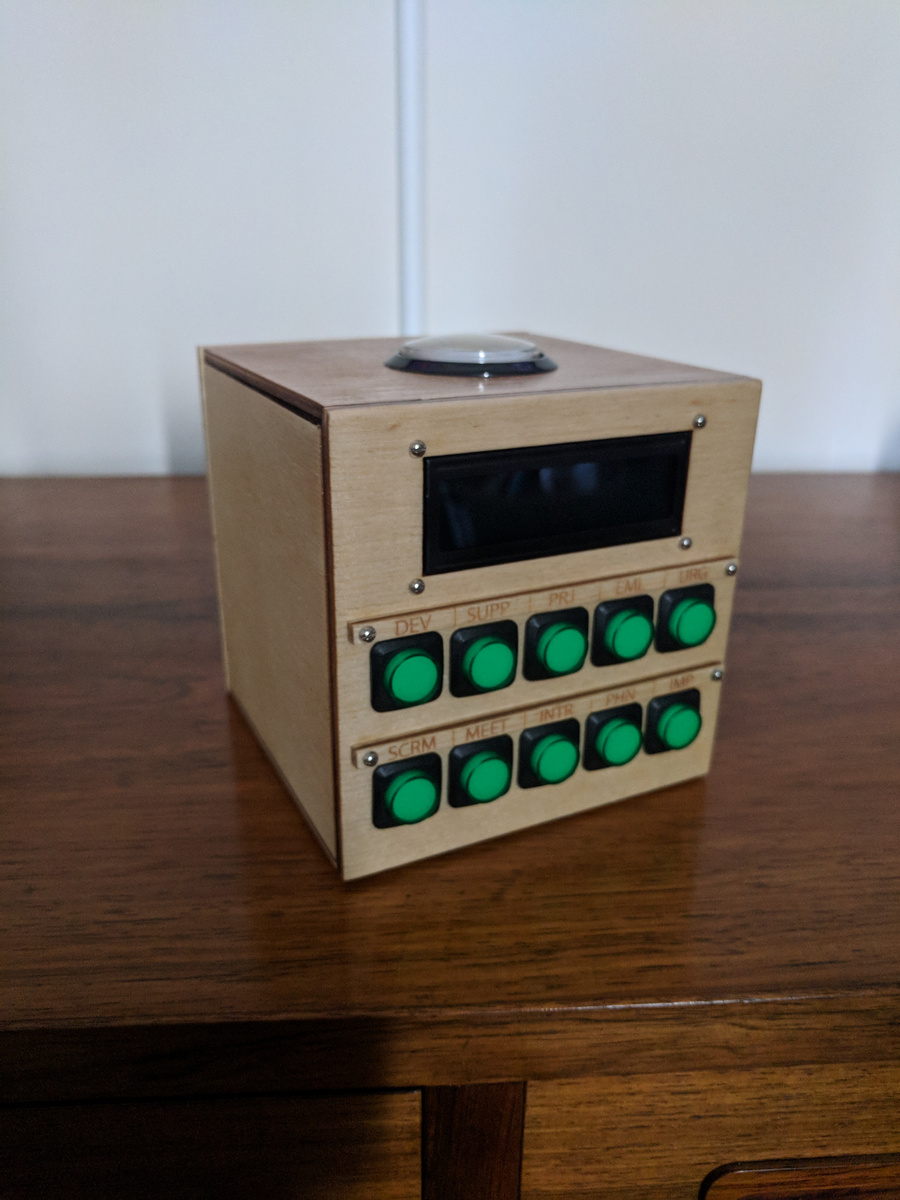
I came up with the idea of using “category tags” as the input method. This consists of a short list of tags which can be used in combinations to describe the current activity:
-
DEV: Development -
SUPP: Support -
PRJ: Project -
EML: Email -
SCRM: Scrum -
MEET: Meeting -
INTR: Interrupt -
PHN: Phone call -
IMP: Eisenhower’s “Important” -
URG: Eisenhower’s “Urgent”
For example, generally the first thing I do in the morning is check and respond
to emails, this activity is generally just tagged using {EML, IMP}. Inevitably
during the morning, my phone will ring and it will be either my boss or another
manager asking for some information, I may tag this activity as {INTR, PHN, URG}.
Also every morning we have a team Scrum meeting; I made a shortcut tag for this,
but it could also maybe be described using {DEV, MEET, IMP}.
As you can see, there are quite a few interesting tag combinations which can be
used to describe developer and developer-manager activities. I can also
automatically derive the Eisenhower quadrants according to whether the IMP
and/or URG tags were specified.
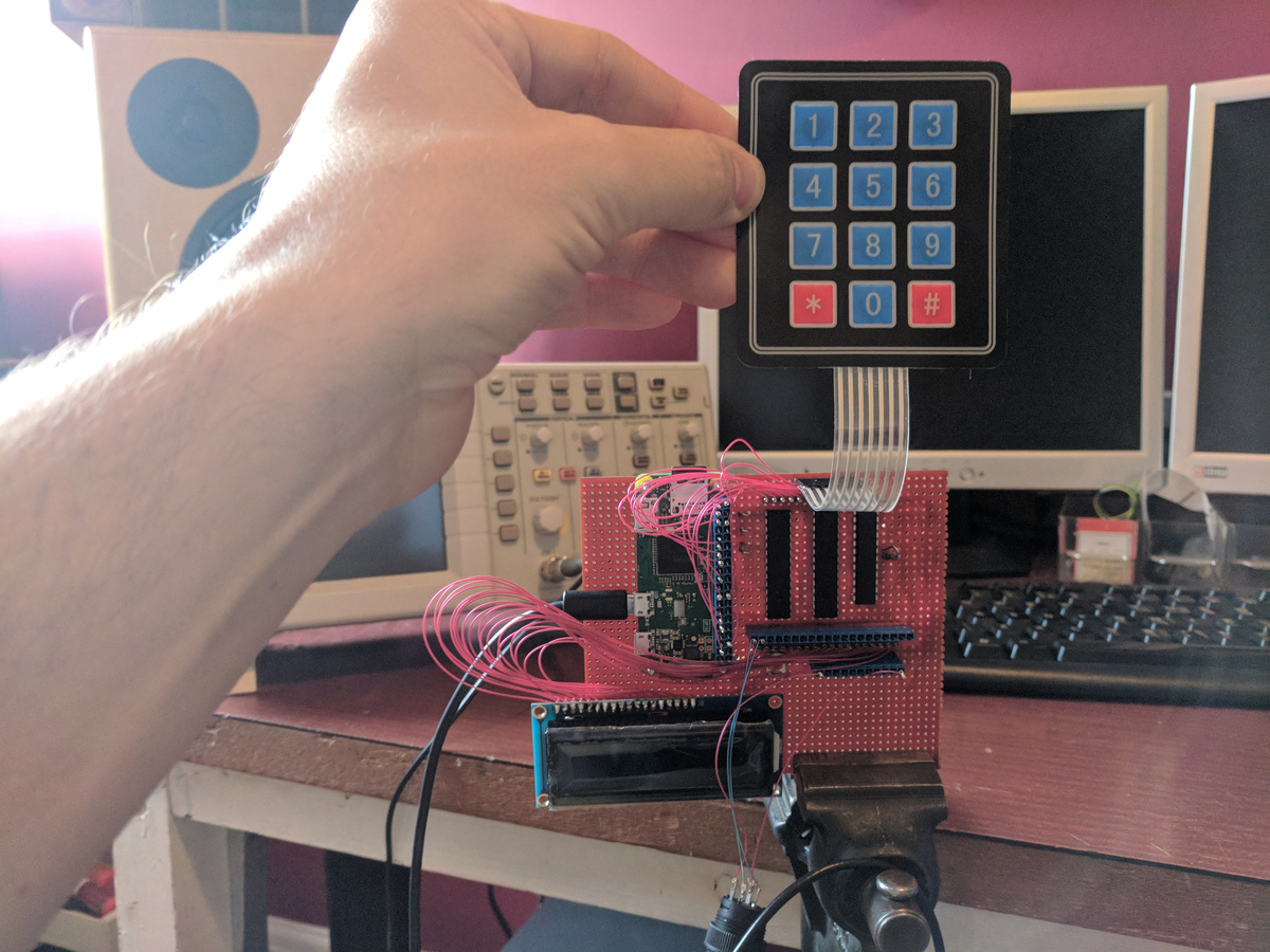
I originally also thought a numeric keypad would be nice in order to input specific task codes, however I couldn’t really justify this in the end as it adds a lot of complexity and a number alone is not sufficient to identify tasks in the long term. That and the fact that I do not really do very many development tasks with actual code reference numbers any more. It was a bit of a relief to drop this feature and arrive at a solution which is much simpler. Having the keypad interface also made the physical size of the device uncomfortably large. By dropping this feature though, I would lose the ability to track time spent on individual projects, but as a developer-manager now I rarely contribute any direct development input into projects any more, and I would rather focus on tracking my own overall efficiency across all of the activities I have to perform.
One thing I needed to replace though was a way to “accept” the tag inputs. I originally set out to use the keypad’s “#” and “*” buttons for “accept” and “cancel” respectively, but now I needed something else.
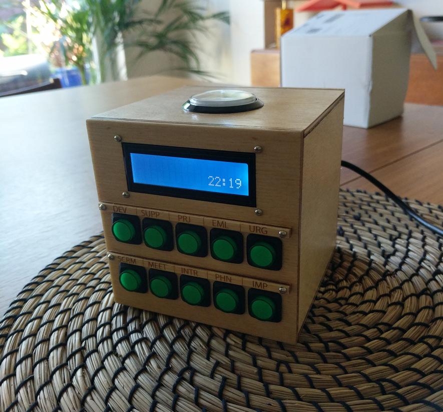
I knew, however, from the start that I wanted physical buttons for the tag inputs, and a colour-changing LCD screen as the display. I’ve used such a screen before and like the retro style. This alone led me on to a sort of cool, retro arcade-machine look for the final physical product.
Ah, an arcade machine. How about a comically big illuminated push button on the top for “accept” ? Perfect. As it turns out, I also could happily remove the “cancel” button altogether without affecting functionality.
The original “specification” sketch above also calls for a Raspberry Pi, and LED illuminated push-buttons. I chose the Raspberry Pi Zero W as the heart of the application, which also necessitated a couple of other accessories to support the other hardware; 2x MCP23017 GPIO port expanders and a MAX7219 LED driver.
Prototyping
Being familiar with Python and Qt, I quickly threw together a PyQT mock up of the physical interface.
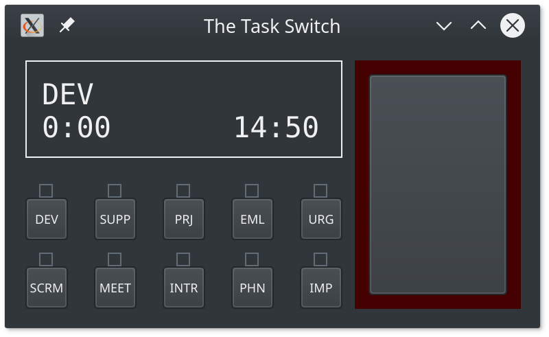
I decided to reduce the number of inputs from that shown on my initial sketch. I did not need dedicated accept/cancel buttons, and I could only come up with 10 useful tag buttons. The only other interface features are a single action button and a 16x2 character “LCD Screen”. It didn’t take very long at all to write the application logic and have something which I could test!
I had to build the prototype application in an
MVC pattern
(naturally), knowing that I could simply implement a second V for the physical
hardware interface. This turned out to be a good thing to always keep in mind,
as I was always conscious of exactly which parts of the application code and
logic belong where, I definitely did not want to have to duplicate any code when
I started on the hardware interface “View”. In the end, I actually allowed the
C to plug into multiple V at the same time, this was invaluable for testing
the hardware, as I could click a button on screen and see the same state
reflected on the hardware (and vice versa) - that was a good way to ensure I had
correctly set up the hardware button inputs and that they all worked correctly.
The M in the system is an output-only class writing the activity log to YAML
file. This was later extended to be able to read back the last logged item when
the system restarts, and also to read the entire log for web syncing much later.
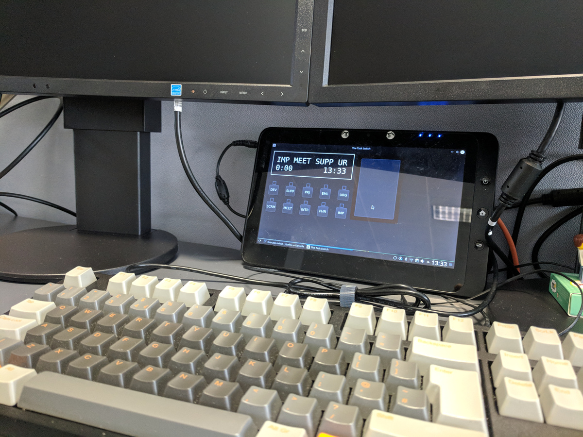
However, before embarking on any hardware build, I wanted to ensure that I had the interface and UX as per my primary goal. I needed to get my prototype application on to my desk to start using immediately. I have a small x86 tablet (Viewsonic Viewpad) kicking around from some years ago, so I thought it would be a good idea to test the app on it on my desk as I developed the rest of the physical object. I installed a fresh Linux (Kubuntu) on it, cloned my app and was up and running.
Within a week of having the idea for this project, I had something already working and on my desk to replace my notepad and pen.
My last real notebook entry was on 8th March 2018, and the note for the following day reads “time logged digitally :)”. Indeed the first records in my YAML log files start on 9th March 2018.
Note that I have only been working on this project during some lunch times at work, and a few evenings or weekend afternoons at home. The rest of the journey below to make the device real took around 3.5 months.
The Software
Operation
So, how does the software work exactly? The primary function is to input a combination of tags.
The initial state is that none of the buttons are lit up, and the LCD screen displays the current time.
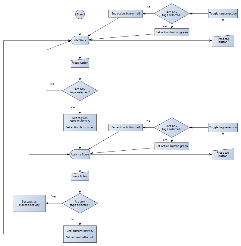
One just has to press the relevant tag buttons (each one lights up as you press it) and then the “action” button to start the timer. During this selection phase, the action button turns green to signal as “accept”. Once the activity has been accepted, the selected tag names and the activity elapsed time is shown on the LCD screen and the action button is red, to signal as a stop function. The LEDs in the tag buttons also turn off. The timer keeps going until you press the action button again.
My number two UX requirement is that it needs to be not distracting at all times.
Therefore, most LEDs are normally off and only used during the time of input. Whilst the activity is running, the action button’s red colour intensity is actually lower than normal.
If you did not select any more tags before pressing the action button (i.e. you press it in the red state) then the activity is ended.
If you selected more tags before pressing the action button, it first turns green (to signal a start action) and then the timer starts on the new activity.
If there is no current activity, the timer displays the idle time as a negative value, and the action button is not illuminated.
The LCD screen also flashes up “OK” (in green) or error messages (in red) on input.
There is only a small amount of validation built into the software - you cannot
select only IMP and/or URG tags, you have to also specify at least one other
tag. It will also display an error if the internal YAML file could not be written.
That is it for the human interaction part. The only other function which the device performs additional to the original specification is a periodic sync to a web service, during which time the LCD screen turns blue (and can flash a red error message if this fails).
Structure
The code is written in Python, and I structured the project as a single python
package called tts. There are three sub-packages in tts:
-
tts.core: contains the controller, models, state management and validation -
tts.ui: contains the views; _tts.ui.desktopwith the PyQt widget interface, _tts.ui.hardwarewith the hardware interface and device drivers -
tts.net: contains the web API sync code
The controller receives events from the UI view(s) and uses those to update the application state model. The state model emits its own events, and these are dispatched out to the storage model or back to the UI view(s) as needed.
Redux state model
Given that I am primarily a web application developer(-manager), I have recent experience using React and Redux. I have really like using Redux for application state management, the strictly functional programming approach to this makes a lot of sense and I have seen it used effectively to provide a robust way to manage application state. I wanted to make use of this in this application instead of having some ad-hoc states in the controller.
Making a python (or any) clone implementation of this is remarkably simple. The
main Store class is but 30 lines of code; including support for middleware.
## https://bitbucket.org/doughammond/the-task-switch/src/08ee4e427055129b4cc39d4f9219dd9e75834a90/tts/core/redux.py#lines-60

class Store(_Qt.QObject):
	newstate = _signal(object)

	def __init__(self, reducer, *args):
		super(Store, self).__init__(*args)
		self.__reducer = reducer
		self.__state = None

		self.__dispatcher = lambda action: self.__single_dispatch(action)

		# ensure we have a default state
		self.dispatch({ 'type': None })

	def apply_middleware(self, middlewares):
		d = self.__dispatcher
		for m in reversed(middlewares):
			d = m(self)(d)
		self.__dispatcher = d

	@property
	def dispatch(self):
		return self.__dispatcher

	def __single_dispatch(self, action):
		self.__state = self.__reducer(action, self.__state)
		self.newstate.emit(self.__state)

	def subscribe(self, slot):
		self.newstate.connect(slot)

	def getState(self):
		return self.__state
I am certain that my implementation is not as thorough as the canonical javascript one, but it uses the same principles and works well enough for this application. Here’s an example usage:
def reducer(action, state=None):
	state = state or {}
	if action['type'] == 'SET_FOO':
	  state['foo'] = action['value']
	return state

store = Store(reducer)

@_slot()
def state_handler(state):
	print('foo is: %r' % (state.get('foo'),))

store.subscribe(state_handler)

store.dispatch({ 'type': 'SET_FOO', 'value': 'bar' })
Hardware device interfaces
I didn’t want to get too far down into the nuts and bolts of IO devices, so I opted to make use of an existing library, WiringPi. There is a pretty good Python binding for it, and also includes an interface for the MCP23017 and LCD, so I only really had to make quite thin wrapper classes for the devices I wanted to use. The implementation for the MAX7219 is a bit more manual, where I am ‘bit-banging’ the serial protocol myself.
I wanted to make use of the device interrupts on the MCP23017, so that I could
efficiently detect button pushes. Unfortunately, the particular combination of
WiringPi interrupt handling code bound through Python running a Qt event loop
make this more or less impossible to get working. The obvious way of hooking this
up ended up SEGFAULTing Python :(
I resorted in this instance to polling the chip’s port state and using the software to report when the state changes; hence StateScanner. The StateScanner is actually generic, it can periodically call any function to get a value to detech for changes. It is all a bit inefficient still, but the Python version of the application is still somewhat in the territory of being a prototype. It is good enough to prove that the electronics is wired up correctly and watch the device work.
Repo
The code for this version of the software can be found here:
bitbucket/doughammond/the-task-switch
Building the Electronics
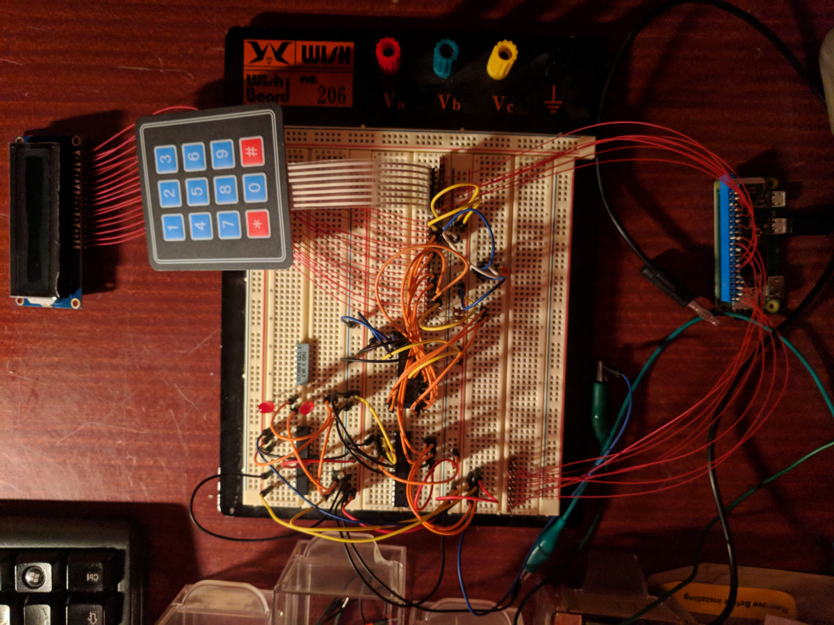
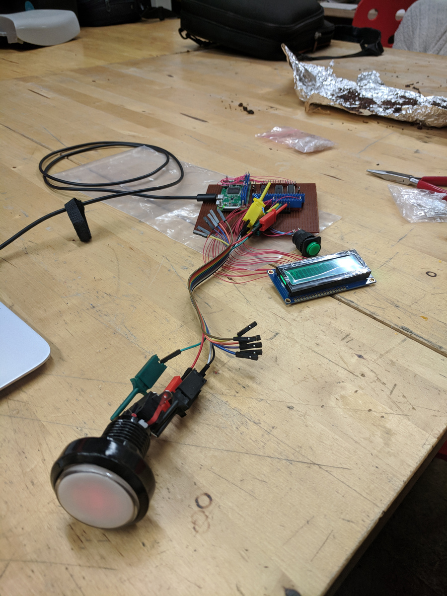
The first step into the real world involved figuring out how the components work and how to interface them. Bring out the breadboard!
(Apologies that this section reads a bit like a holiday photo album, but fortunately I did take quite a lot of photos of various stages of the build, and I think that they mostly speak for themselves).
Before that though, I had to decide which GPIO pins on the Raspberry Pi I can use for each device. I used KiCad to make a schematic.
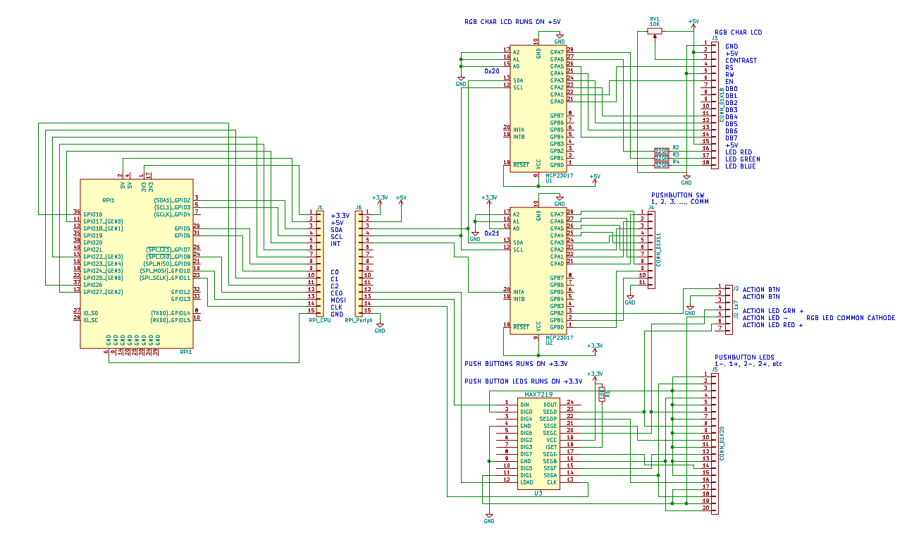
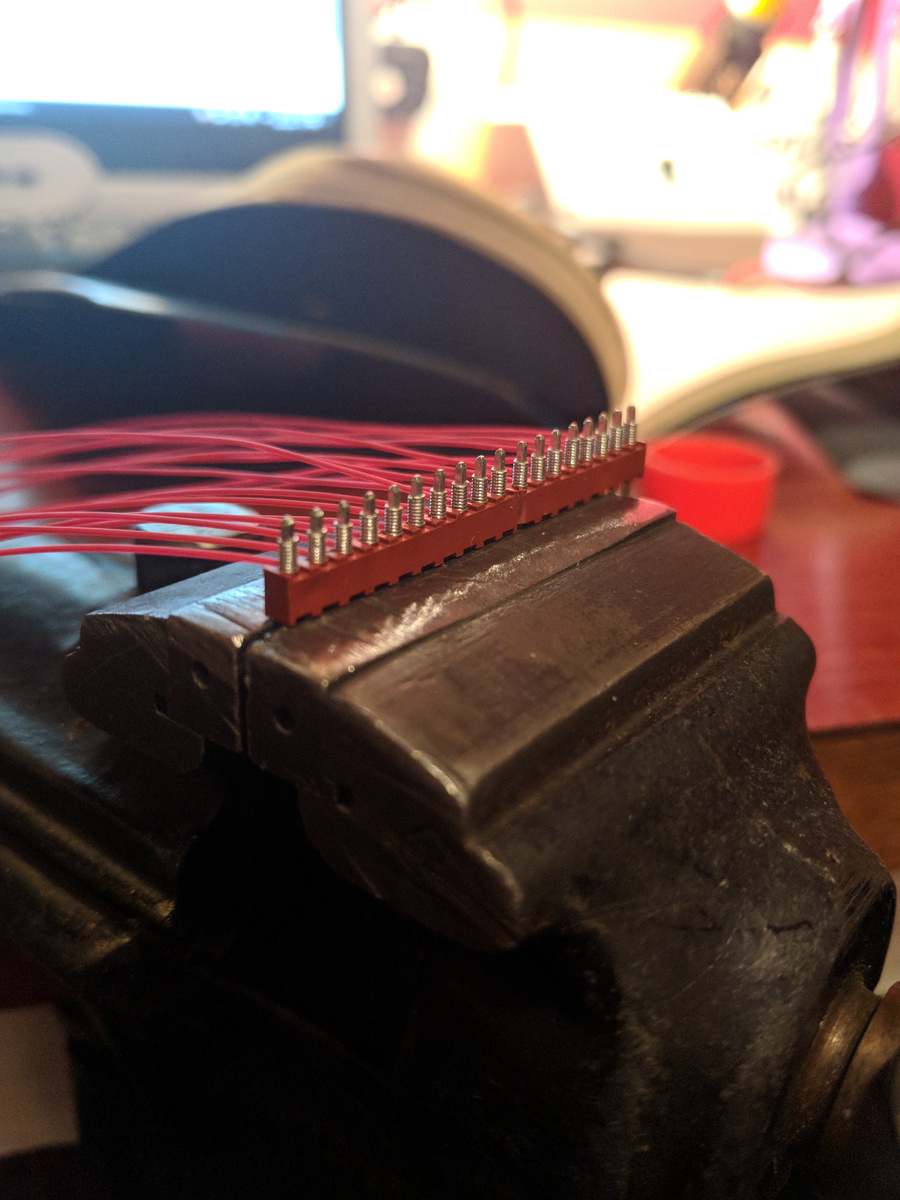
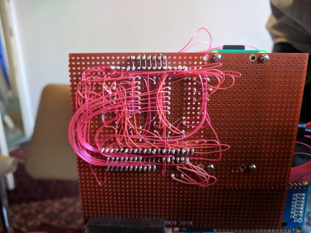
Knowing that I may have to change a few things around as I went along (that and the fact that I cannot manufacture PCBs), I went with a wire-wrap approach to connecting things together. This is a somewhat old technology for semi-prototyping connections, and it also so happens that I have a large stock of old wire-wrap wire and the right tools to use it.
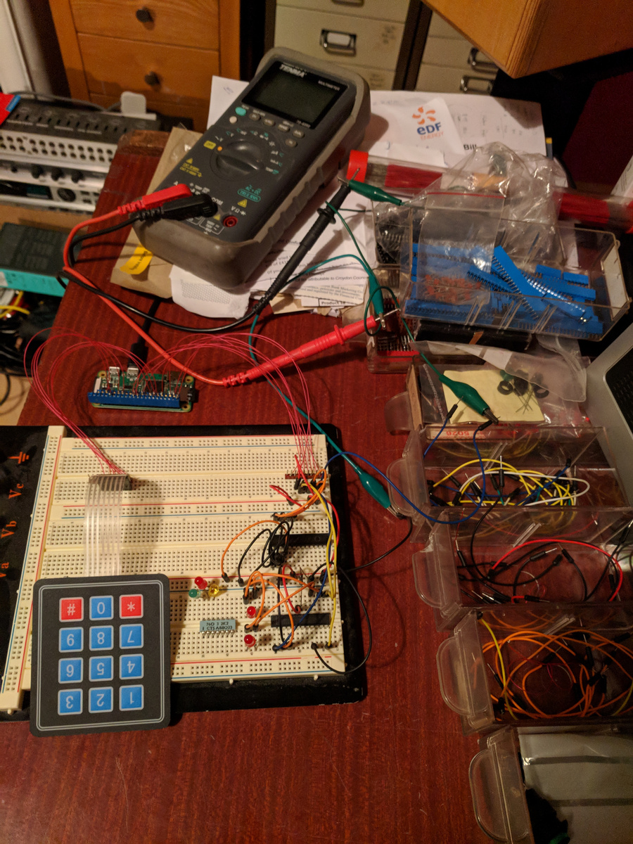
Eventually I had most of the system hooked up on the breadboard. It stayed this way for some time whilst I wrote the software View to drive it, there were quite a few iterations of device drivers and interfaces before I settled on something which seemed to be working.
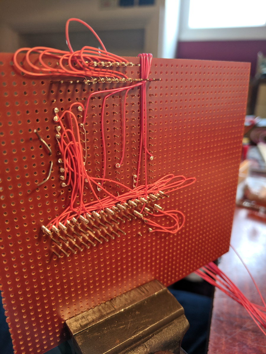
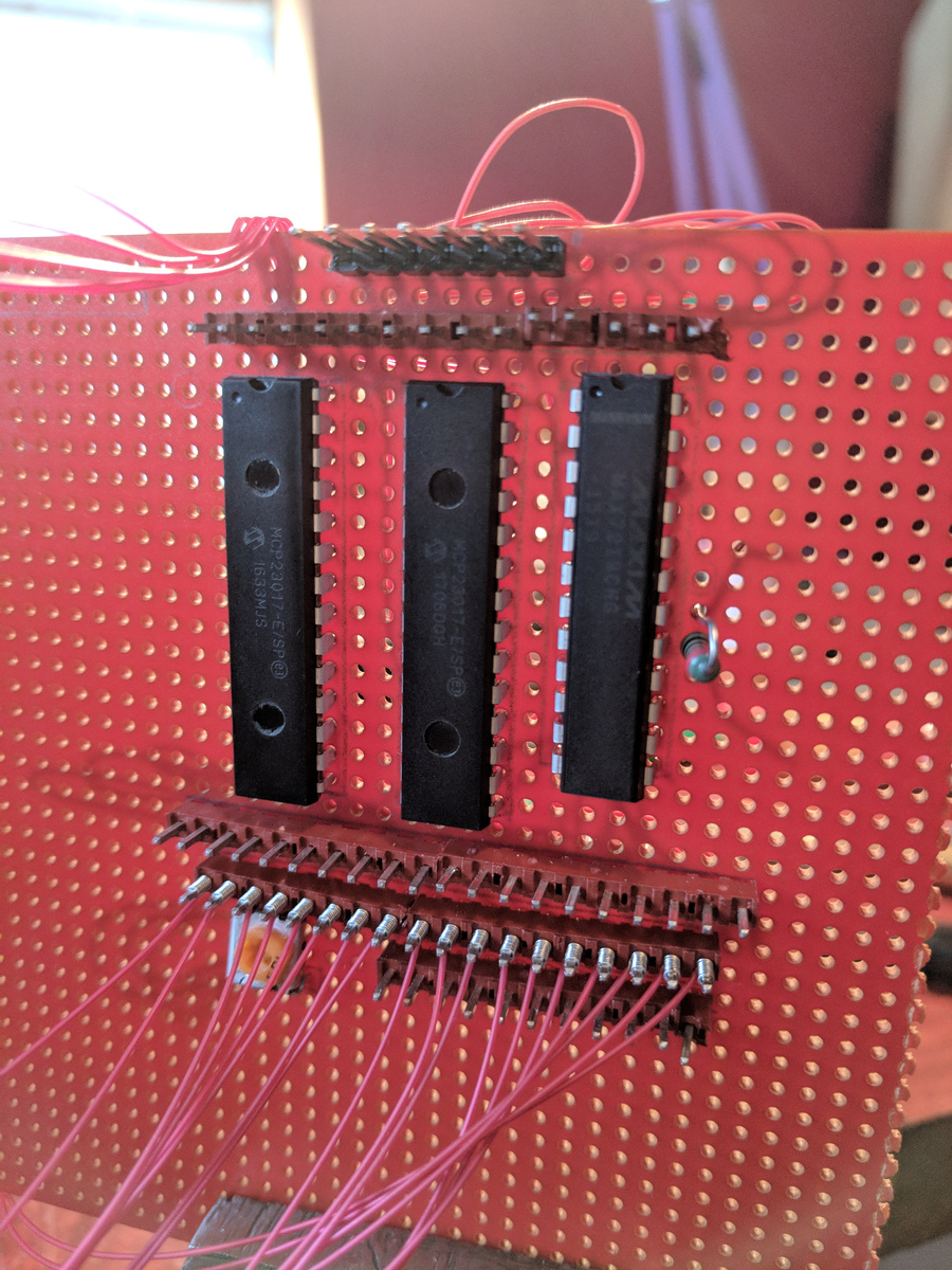
Before long though, the components had to move on to a “real” board. More wire-wrap. This was the first “layer” applied to hook up the LED driver chip:
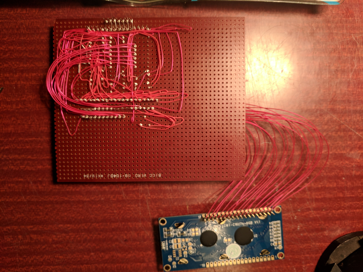
And after a couple more “layers” and with with with the LCD attached. If I were to do this again I would perhaps not permanently attach the LCD wires to the board but use a connector like I did for the other peripherls.
I actually got quite a way along the hardware build before I decided to drop the keypad feature. It was only really at this point that I could really tell that it would be both cumbersome to mount properly and that it was not worth the effort. At this stage I also thought the Pi would be mounted on the board, that turned out to be impossible if I wanted to have the minimum size cubic box, though mostly because the USB lead connecting to the Pi would collide with the side. The Pi itself would fit on the board within a 114mm square.
Connecting up the first illuminated button:
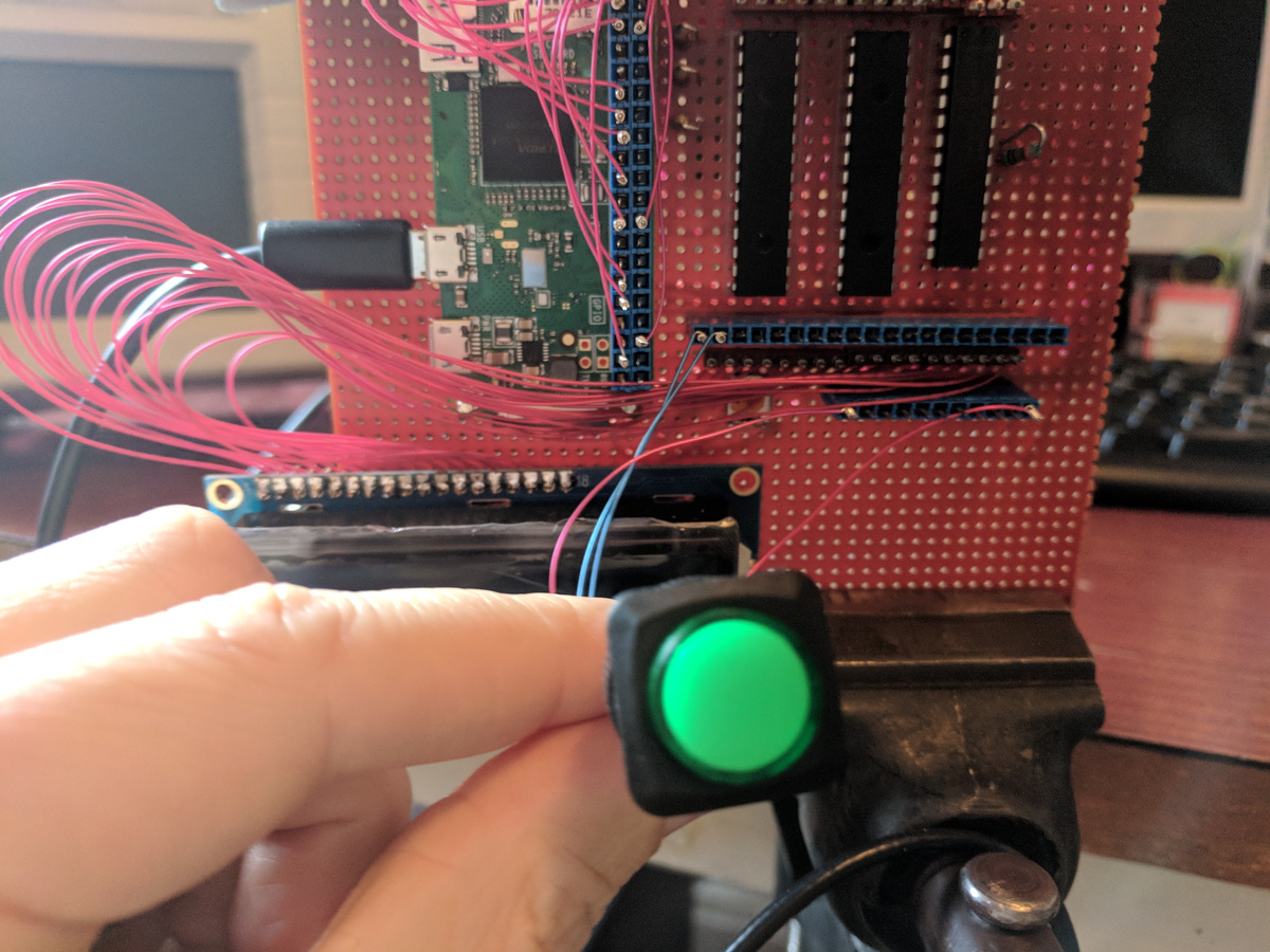
The arcade button I sourced had originally just a plain white LED mounted inside. I knew my application required a colour changing status indicator, so I pulled the button apart and replaced the LED with an RGB one. I removed also the metal contacts which hold in the original LED, and threaded the legs of the RGB LED down through the holes left in the casing. The microswitch clipped into the bottom of the housing clamps the LED legs in place. Here I was testing the same LED on the bench at South London Makerspace:
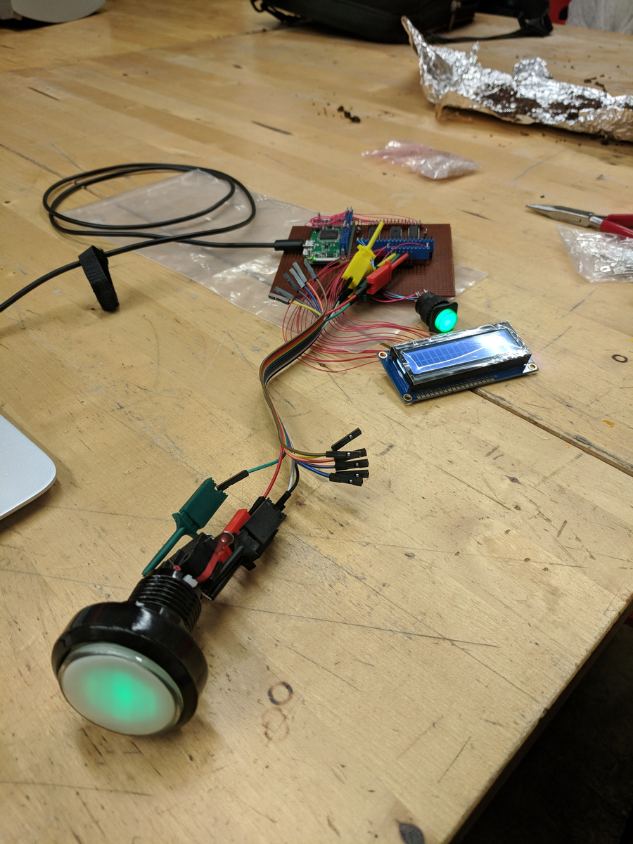
By this point I had build the electronics and proved it worked. Time to box it up into a usable device.
Building the Box
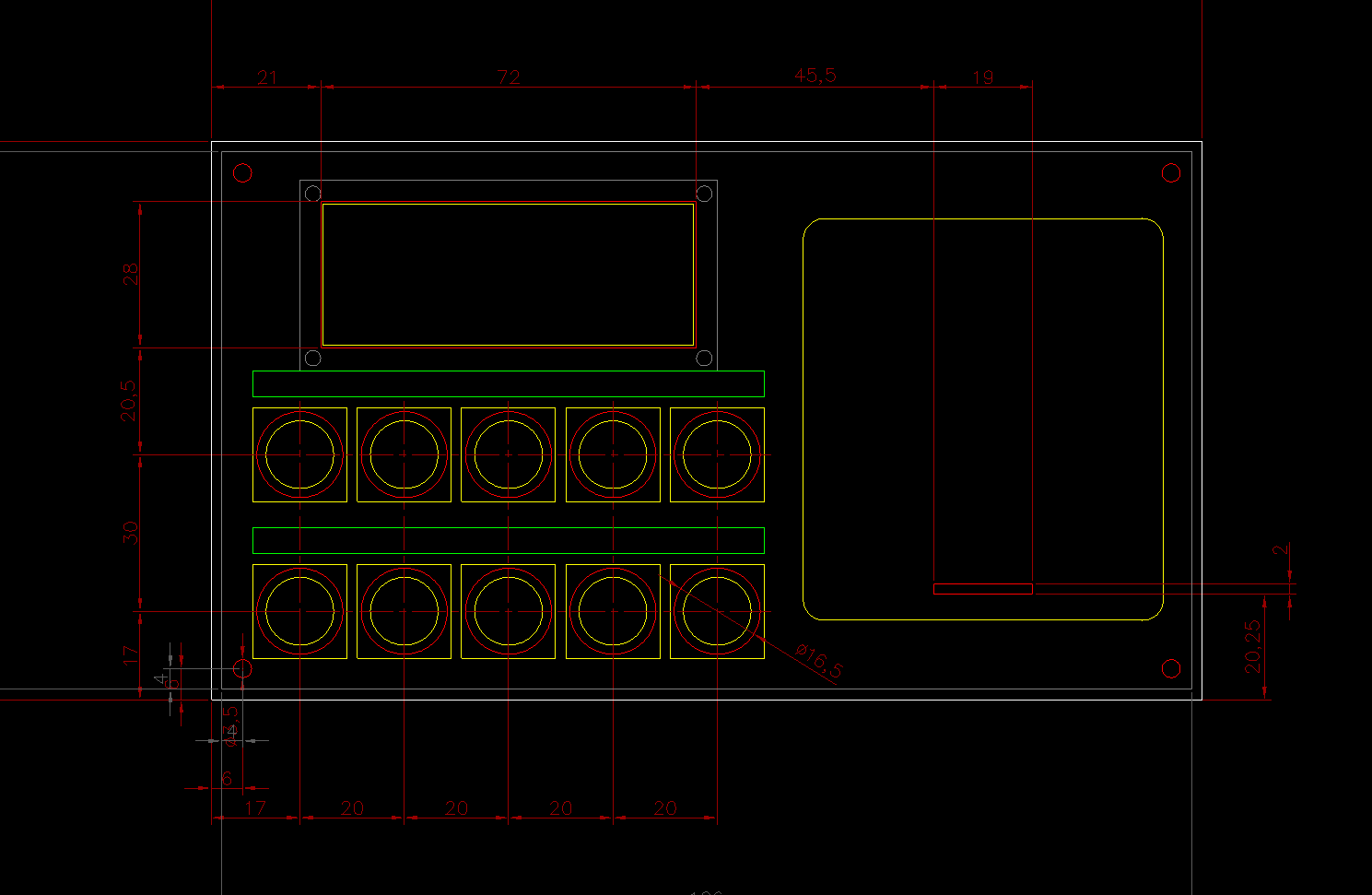
I started out with CAD of the front panel, by now trimmed down to the bare essentials:
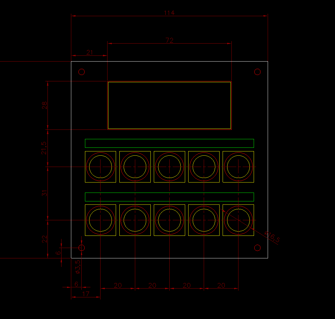
I originally just left some space above the buttons to stick on some printed labels. I later revised this idea and make the labels out of wood and fixed them on with some cute shiny 8BA bolts.
This set the minimum possible size at around 114mm square at the front. My next thought was to make the box a perfect cube, though that took quite some time and a lot more drawing to figure out if that would even be possible. Turns out is was.
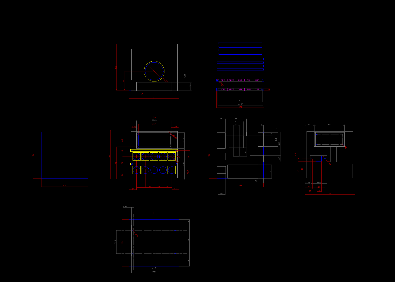
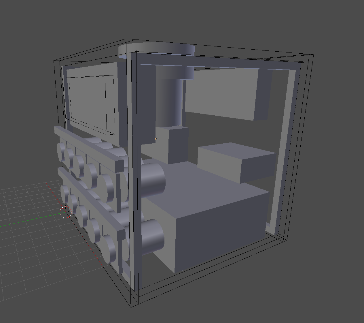
I verified the CAD drawing dimensions by making an actual 3D model of the box panels and internal components. Yes, I did have to really measure all of the components and the circuit board, and yes I left a little margin in the measurements to be better safe than sorry. The components were proven to fit:
The next step was to cut out the wooden panels somehow from the CAD drawings to make a box. Being a recent new member of South London Makerspace I gained access to their Trotec laser cutter, which makes light work of cutting out and putting holes in ply wood. It also can engrave, which was a handy solution to the button labelling problem. I had to arrange some thin wooden strips inside the box to hold the sides together, and after some quite intricate glueing and clamping, I have now a quite pretty little box.
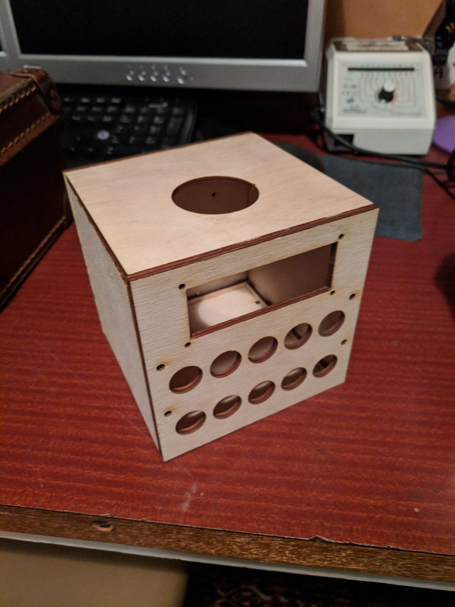
I have to admit though that it is not perfect. The CAD drawings assumed the ply wood to be exactly 4mm, but in reality the material is a little thinner. I did not know this before cutting commenced, so some of the sides do not meet exactly. I accept that as the first attempt at building something like this, I just will not look too hard at the left side whilst using it :)
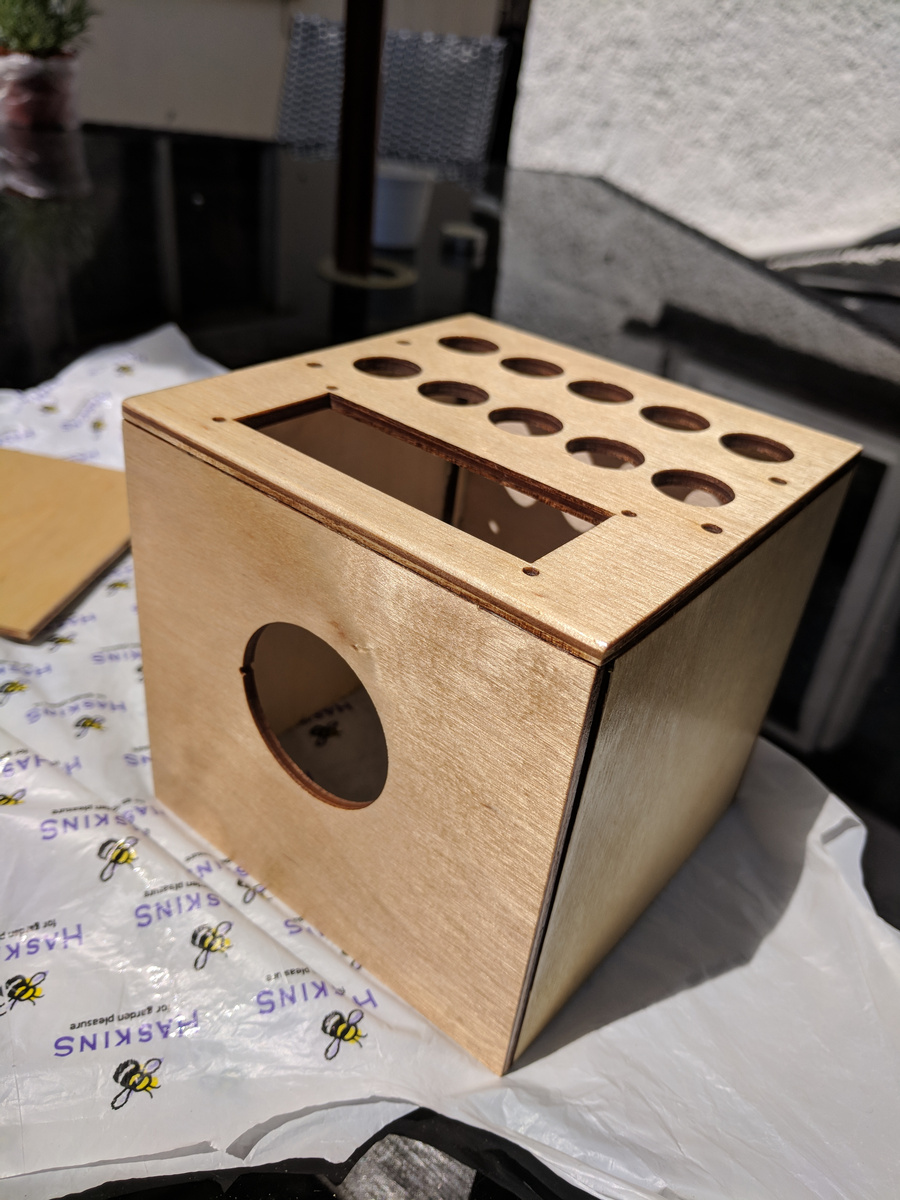
After sanding the burn marks off, and oiling the wood in the sunshine, the box actually started to look quite attractive:
And finally with the components installed, except for the rubber feet on the bottom. Never mind the gap on the top left edge.
CAD Files
bitbucket/doughammond/the-task-switch/src/master/hardware-dwgs
Software Rewrite
Now that I was ready to run the software with a full set of real hardware, I naturally updated the Python/PyQt code on to the Raspberry Pi and tried it out. I was rather disappointed, even more so than expected because I knew that the Python hardware driver code was somewhat inefficient.
There was a massive latency between pushing a button and having the application respond. Latency in the range of seconds. I tried quite a few tricks to try and get to the bottom of this, but eventually came to the conclusion that perhaps a tiny Raspberry Pi is not the best platform for running Python code, or that my choice of using C/C++ libraries via Python bindings in a single threaded runtime environment was just the wrong choice. I am not at all trying to say anything bad about Python though - it had served me very well in figuring out the prototype in a short space of time and to prove the worth of the project. It was just time to try something else.
I decided to re-write the entire application software in C++ Qt.
This way, I could very closely follow the Python implementation, but take advantage of using Qt and WiringPi in their natural environments. It took a fair bit longer than expected, I was a bit rusty with C++ and there were some road-blocks also in actually compiling the application for the Raspberry Pi.
At first I was not satisfied with having to compile on the Pi, it really is not fast enough. Therefore, I had to get hold of a cross-compiling environment on my laptop to speed up the process. Thankfully Qt Creator makes setting this up actually very easy from the IDE’s point of view, but there was still some work to do to get a working compiler set up with a cross-built Qt and a basic sysroot from the Pi.
Here’s a bunch of resources I found useful:
- Cross compiling Qt for Raspberry Pi
- Cross-compilation guide for Qt 5.9.4 and RPi
- Overcoming a compilation issue regarding ICU library
Structure
This version of the application became structured into 3 library and 2
application projects, tied together using a Qt subdirs master project;
-
redux: (Library) Another simple Redux implementation -
tts-core: (Library) Contains much the same stuff as the Python implementation packagestts.core+tts.net -
tts-devices: (Library) Device driver classes -
tts-gui: (App) Desktop UI View and application -
tts-pi: (App) Hardware UI View and application
I also wrote two small test projects to help get the implementations working:
-
redux-test: Test suite forredux, using QtTest -
devices-test: Test suite fortts-devices, not really a test suite, but more of a harness to be able to call functions on the device driver classes
This implementation does still support using more than one View class at a time
with the Controller, but I never yet actually had to. I used tts-gui to develop
the Controller implementation on the desktop and tts-pi could make use of that
whilst I developed the device drivers.
Redux again
The implementation of Redux in C++ ended up a bit more verbose than in Python. Writing it again though was an experience worth having, having a strong type system made me really think about interfaces and how to make the Store, Dispatchers (middleware) and Reducers composable in a way that works.
The state of the application,
however, is implemented using QVariantMap. This is still a compomise in the
design, I am not a big fan of this data type, but I concede that it does work.
Hardware interfaces again
I’m still using WiringPi in this project, but this time it’s C interface. Thus, the device driver classes in C++ are much the same wrappers as I had in Python.
One key difference is the interrupt handling. By this point I had actually realised I can use a slightly different approach. I hooked up the MCP23017 INTA pin to a Raspberry Pi GPIO and I instead poll that state instead of polling over the I2C bus. Thus, the InterruptWorker still polls a state, but rather more quickly. I am still aware of a bug in this implementation, but not exactly what the cause is. Sometimes, the code or the device does not read and reset the interrupt state and gets stuck. I implemented a work-around using a timeout and reset condition to force this to happen if it detects it gets stuck.
The end result though is much reduced input latency. The push buttons appear to respond instantly to touch :)
Repo
This version of code can be found here:
bitbucket/doughammond/the-task-switch-qt
Unexpected Issues
There are still a few bugs in the system that I know of, and probably a few more that I am not.
I notice that some of the push button LEDs (actually, mostly one in particular, INTR)
comes on and off and flashes randomly. I don’t know the exact cause of this yet,
but must be something to do with the MAX7219 since there is no activity in the
software when it happens. There is probably a floating logic line or noise on
the serial bus perhaps.
I’ve also noticed that some of the “temporary status” messages, particularly those shown during the web sync process do not display for long enough. I suspect multiple status changes are happening within the status timeout period, there is no code yet to queue these to allow the user to read every status.
Web services
Having the application keep a record of activities locally in a YAML file is fun for a short while, but once the device is all boxed up and working there is no easy way to extract it for processing and reporting. Also, why should I have to do that ?
The Raspberry Pi Zero W was chosen as the platform for a good reason. “W” stands for “WiFi”. Once configured with access point details, the application can just upload the data itself to a web service.
So, how did I go about doing this ? Bring out the Python again !
The library of choice this time is Flask, a self-proclaimed micro-framework for building web apps (and also APIs). Since I was to build an API only, I also made use of Flask-RESTful as the Resource interface.
I still need some storage for the data, so bring in Flask-SQLAlchemy and Flask-Migrate. The API needs also to be secured, so also bring in Flask-Security.
Overall, I am impressed by the community of libraries surrounding Flask, however I’m not that impressed at the default way of structuring a Flask project. Almost every example usage shows the entire application in one file, without any real separation of concerns. Even if one is to try and split the project up into modules, you’ll also quickly run into a situation where you are required to use circular imports. Quite a lot of fiddling is required to structure the project correctly and with a chain of dependencies/imports which makes sense.
Even after all of that, I still did not have Flask-SQLAlchemy and Flask-Migrate
working correctly together. There was some trickery with patching in something
called a metadata object on the various interfaces which allow them to share
a confguration. That was really not intuitive at all.
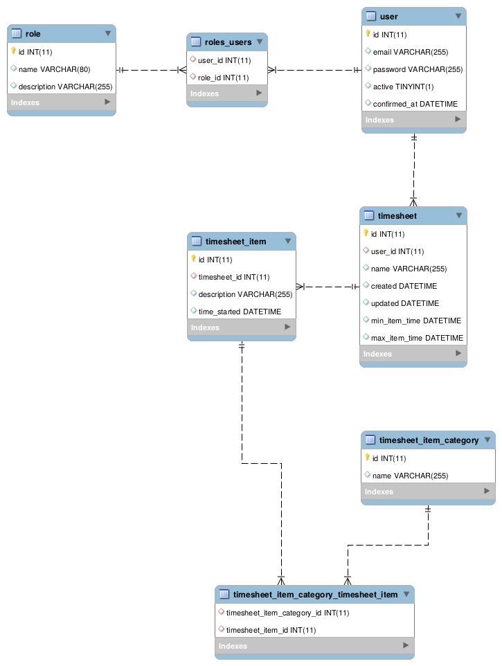
Data Model
The database only has a handful of tables. A couple for user and role
required by the security implementation (which also, helpfully, enables a hosted
instance of the API and report to be eventually be useful to more than one
person at a time). The other 4 tables are:
-
timesheet_item: A timesheet line-item; in other words a single activity -
timesheet_item_category: Normalised table for storing tags used bytimesheet_items -
timesheet_item_category_timesheet_item: Many-many pivot table betweentimesheet_itemandtimesheet_item_category -
timesheet: A grouping oftimesheet_items into a daily “time sheet”.
REST API
Due to the relative simplicity of the above model, the REST API is correspondingly
quite simple. All that is really required is to make a request to PUT timesheet_item
and the code will:
- Check if the item being sent already exists and re-use or update it and the related categories as necessary,
- Generate or re-use an existing
timesheetgroup for it
And that it about it. There are a couple of GET methods to return your data for
the purposes of the Reporting application.
Repo
bitbucket/doughammond/the-task-switch-db
Reporting
The Reporting app is actually the first part of this endeavour that I created. It was originally built to analyse my manually input YAML files. It is built using React and Redux.
The original structure of the YAML data was a little simpler than the current data model. Each timesheet item originally only had one category, however I extended that to multiple. Because of this, the report app now is still incomplete because I need to change some of the aggregation and widgets to support multiple categories. As a result of this, there is also some legacy in the data model throughout this project which can eventually be cleaned up (e.g. timesheet item description).
The application does work though to produce a pie chart and daily breakdown of Eisenhower Quadrant percentages. The detailed timesheet listing also works fine.
I would like to replace the initial pivot table with something a bit more time-line based, which can show the individual tag active periods over time, probably with colour coding for the Q numbers.
Repo
bitbucket/doughammond/timesheet-report
Finished Project
So, we’ve arrived at the bottom of the page, I suppose that warrants a conclusion of some sort.
I’m considering this project more or less done for me for now. I will aim to fix up the Report a little, but I personally don’t require much more.
I learned a fair bit in the process, mostly in the world of the hardware, which is what I set out to achieve. Particularly with regards to doing CAD for manufacture, even if that manufacture is of a somewhat simple automated laser-cutting variety. I may revisit the box at a later date as well, to fix a few issues:
- The current box fits together properly, but is not exactly a neat job
- The LCD viewing angle is not correct when the device is on my desk. It would be better to be tilted upwards nearer 45 degrees.
- The top panel of the box is a different wood & colour than the rest. Though you probably wouldn’t have noticed if I had not mentioned it, it makes the box just a bit more less perfect than it could be.
At some point it might also be fun to make a proper PCB for the board, instead of using wire-wrap. That might be the cause of the random-flashing-bug if I’m perfectly honest.
It’s Open Source !
If you think you’d like a toy like this one, then you’re in luck. All of the code and design material is open source. You can clone, copy, adapt and even submit patches back to me if you wish.
- Python software implementation the-task-switch
- (This also contains the CAD drawings and schematics.)
- Qt software implementation the-task-switch-qt
- Web service the-task-switch-db
- Report application timesheet-report
Acknowlegements
I couldn’t have done all of this so quickly without all of the below. Thanks all :)