Programmable Synth Controller
Table of contents
- An interface for the box that goes bleep
- Requirements
- First iteration
- Second iteration
- Third iteration
- Evolution of the psc
- Wait a sec, what did I learn exactly?
An interface for the box that goes bleep
As soon as I started thinking about building my own synth, I built into that project the requirement to interface the synth with a computer using MIDI. After all, that's what I know for generating notes, and I didn't want to start building analogue keyboards or sequencers to make the synth work standalone. This interface became known as the Programmable Synth Controller, or psc for short.
Requirements
Synth Control
To figure out what we need, lets work backwards from the synth itself. The interface to the synth modules is a simple voltage level, via the "CV" (Control Voltage) inputs on the modules. To have the computer control the modules, then what we need is some way to convert a MIDI message into a voltage. The voltage can be set using a DAC (Digital to Analogue Converter), and we will need some other electronics, namely a microcontroller, to read the computer data and instruct the DAC to set a specific voltage on its output(s). We will also need multiple different voltages changing at the same time, for example one for pitch and another for volume. A couple more wouldn't go amiss as well so that maybe we can change a filter cut-off frequency at the same time.
DAC Selection
I settled on using an MCP4728 DAC; this is a little device which can output 4 different voltages at once, all controlled by a single i2c input. This DAC is also desirable due to its resolution. I had heard that common and cheap 8-bit DACs can be a little limiting for controlling synths, as only 255 different voltage levels may not be enough. At 12-bit resolution we can have 4096 different levels, so we can represent frequency and volume levels a lot more accurately. We will still be a bit limited however, that the DAC cannot output a full range of voltages which may be useful for the synth. We might ideally want an output of -10V to +10V but given the low voltage nature of the psc system, we will only be able to achieve 0V to +3V or so. This should be enough for a start though.
Additional Outputs
As well as continuously variable voltages, it is useful when controlling a synth to have some digital style voltages available. These are commonly called gate and trigger signals. Gate signals will usually be fully off when nothing is happening and fully on when something is happening, e.g. +5V for the duration of a note and 0V otherwise. Triggers are similar but are usually just short pulses which are emitted at the start of an event.
If we have four CV voltages available, then we should maybe also have four gate and four trigger signals each of which is linked to a CV signal. One "channel" therefore consists of one CV, one gate and one trigger all working together. This needs therefore 8 digital outputs from the microcontroller and I elected to use an MCP23017 port expander chip for all of these. Also hanging off this expander is a "master" trigger output, which changes when any of the DAC values change, and an RGB LED.
Computer Interface
On the computer side, I want the psc to show up as a MIDI device when connected to the computer in a plug-and-play manner.
Added Bonuses
I also had on hand an ancient AY-3-8910 chip. Since we'll be using a microcontroller and accepting MIDI data, why not hook this up as well and have some extra noises available? This turned out to be possible, but the first iteration used more hardware to achieve this than may have been strictly necessary.
Furthermore, if the microcontroller can run any code that I write for it, could it not also run autonomously without the connected computer and make the psc + synth combination work standalone? This is where the "Programmable" part of the name came from. This turned out to be an interesting avenue, but ultimately a massive distraction from the main goal. Even though in the end this thing is not really "programmable", I still continue to call this thing psc.
The choice of microcontroller might also enable wireless control, this was explored but in the end discarded due to lack of any standard interface to use on the computer side and concerns over latency.
Yes, MIDI over Bluetooth is a thing, but there's no sensible bridge available on the computer side to make it appear in any/all DAW software automatically?
Display
I figured it would be hard to know what the psc is doing, or how it is configured without a display. So, lets hook up a 1.8" LCD. We could also use some visual feedback regarding note, tempo, etc. So lets also add one RGB LED.
First iteration
Parts list:
- 1x ESP8266 microcontroller
- 1x MCP4728 4-channel 12-bit DAC with i2c
- 1x MCP23017 16 output GPIO expander with i2c
- 1x 1.8" TFT LCD ST7735S
- 1x RGB LED
- 1x AY-3-8910
- 1x Arduino Nano
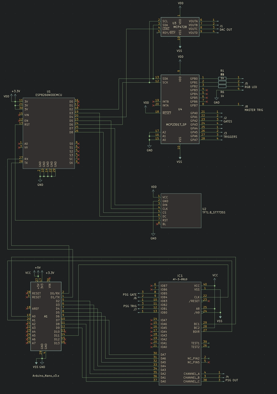
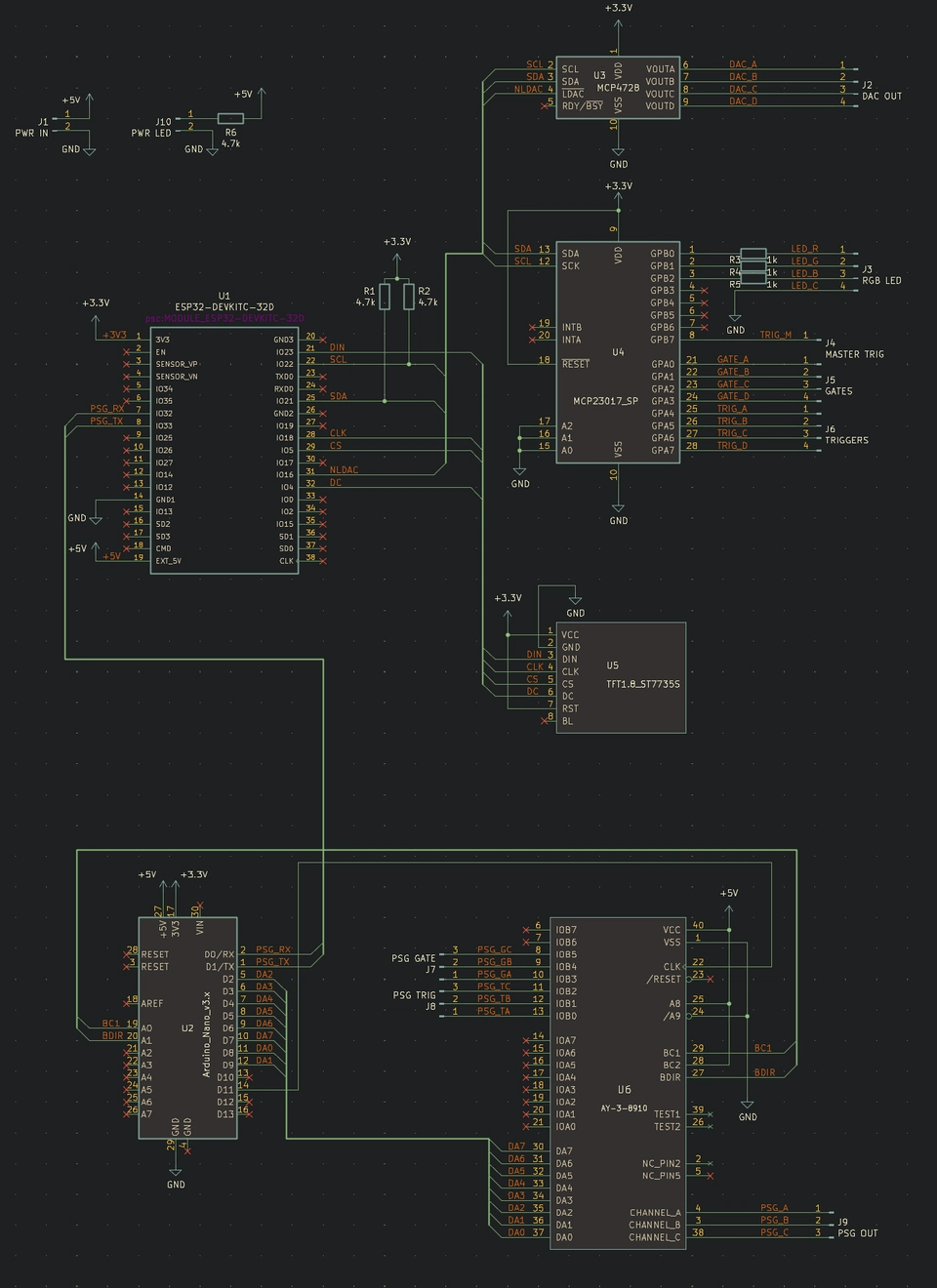
The reason we've included an Arduino as well should be apparent by looking at the schematic. The ESP8266 does not have enough available pins to connect the AY-3-8910. The AY uses an 8-bit parallel bus plus 2 bus control pins plus 1 clock signal, which already would be too many. So instead, we use the Arduino as a "port expander" which accepts AY register data over a UART serial link, and expands that into the signals required to write register data to the AY.
We can just about squeeze all the other primary peripherals onto the other available GPIO pins on the ESP8266.
Fortuitously I also didn't have to write any code for the Arduino, some kind soul on the internet had already done it. In fact, searching now reveals a few alternative to choose from, but I picked up and used this one. This one comes with a small C program you can run on your PC to send "mym" format music to the Arduino, this was actually useful for testing the Arduino + AY combo part of the device in isolation.
ESP8266 firmware
We have a reasonably neat and capable system according to the schematic, but what exactly is it going to do?
Ways to get the MIDI notes as input
Primarily we want to get notes from the PC into it and let it translate those into commands for the peripherals. The ESP8266 is somewhat limited on inputs though:
- MIDI over Bluetooth
- MIDI over WiFi
- MIDI over USB serial
1. MIDI over Bluetooth
There are standards for this, but implementing anything over Bluetooth is an enormous headache. I think I did manage to make it work, but there's little to no support at all on the PC side. I tore this out before too long and forgot about it.
The services definitions I implemented are here.
2. MIDI over WiFi
Setting up the WiFi on the ESP is quite straightforward and we can open TCP sockets to accept MIDI bytes. Again though, this suffers from lack of support on the PC side. Also, we have some hurdles to get over to get the ESP on to the same WiFi network as well. With no keyboard, you can't simply type in WiFi network names and passwords. Pre-installing the password also doesn't really work, you don't want to be re-flashing the ESP just because you moved somewhere with a different network available. Since I started this project though, some newer ways of provisioning ESP WiFi credentials have appeared such as Improv, but they remain a little janky.
There's the final nail in the coffin for transmitting timing-critical musical notes over TCP, and over WiFi is having terrible and unpredictable latency. The notes coming out will simply not be in time with what's happening on the PC. So, lets leave WiFi here and go no further.
3. MIDI over USB serial
This is pretty simple. By default the USB serial is already configured when using common frameworks for ESP devices. We can just sent MIDI bytes down the wire and interpret them one by one. This actually works, if you install and use some MIDI-Serial software on the PC side, such as The Hairless MIDI to Serial Bridge. We failed a little at the requirement of having the ESP itself be plug-and-play with the PC though.
I stuck with this solution, given it's the only viable option really for ESP8266.
Ways to get MIDI notes autonomously
Since I wasn't completely convinced about MIDI-over-serial I started looking at ways the device could just make music on its own. I invented a (very basic!) music programming language which resembles some sort of assembly language. That code could be compiled into a sort of compact byte-code and interpreted on the ESP. Note that this isn't really producing a "machine code" in the real sense that the operations and data directly map to control electrical signals in the CPU, it is simply a compact numerical representation of a sequence of instructions for the device firmware to follow.
pscs
The psc source program format is called pscs. The specification is here. The idea is that pscs defines a set of instructions which can operate on a 16-bit memory address space of 16-bit words, and a way to call "interrupts" which are interpreter implementation specific function calls which may for example accept a memory address and update the state of a hardware peripheral. In this way you can set up and store data and manipulate it with your pscs code, and when the time is right, send some of those values to the DACs.
Note that pscs never defined how exactly any data is input from the MIDI stream or output to hardware devices. The former was implemented as a Bluetooth service working independently of the pscs program running in the interpreter, which required the PC host program to be sending data to psc memory addresses matching what the pscs program expected. To illustrate this, here is the pscs source for live-streaming data:
keyboard.pscs
;
; Realtime input driver for PSC.
;
; The data being input must be written in the following matrix:
;
;            _________DAC__________  _________PSG__________
; Output     DACA  DACB  DACC  DACD  PSGA  PSGB  PSGC  PSGN
; Input      0000  0010  0020  0030  0040  0050  0060  0070
;
; We must copy the input values to this contiguous memory
; segment, and use INT 00 to update the outputs
;
;                  _________DAC__________  _________PSG__________
; Output    Trig   DACA  DACB  DACC  DACD  PSGA  PSGB  PSGC  PSGN
;           00F0   00F1  00F2  00F3  00F4  00F5  00F6  00F7  00F8
;
; @see docs/sequencer-data.md
;
begin:
subscribe:
  INTM 00, 00F0, 00F8 ; subscribe to current data
input:
; compare inputs with outputs
checkF1:
  SUBR 00F1, 0000
  JCN 1, 00F1, trigger ; jump if 00 not equal to F1
checkF2:
  SUBR 00F2, 0010
  JCN 1, 00F2, trigger ; jump if 10 not equal to F2
checkF3:
  SUBR 00F3, 0020
  JCN 1, 00F3, trigger ; jump if 20 not equal to F3
checkF4:
  SUBR 00F4, 0030
  JCN 1, 00F4, trigger ; jump if 30 not equal to F4
checkF5:
  SUBR 00F5, 0040
  JCN 1, 00F5, trigger ; jump if 40 not equal to F5
checkF6:
  SUBR 00F6, 0050
  JCN 1, 00F6, trigger ; jump if 50 not equal to F6
checkF7:
  SUBR 00F7, 0060
  JCN 1, 00F7, trigger ; jump if 60 not equal to F7
checkF8:
  SUBR 00F8, 0070
  JCN 1, 00F8, trigger ; jump if 70 not equal to F8

; if we reached here there was no input, go back and try again
noinput:
  JCN F, 0000, input

trigger:
  ; update output memory
  COPY 00F1, 0000, 0001, 0010, 0008
  ; interrupt to set outputs
  INT 00
  ; start again
  JCN F, 0000, input
end:
As you can see here, it is the pscs program itself which defines how the memory is to be used. I never did figure out how to fully specify this in a way which would allow any arbitrary pscs program to function.
pscc
The byte-code code compiler for pscs is called pscc and was implemented in javascript. I guess at least in javascript the compiler can run on a web page and could therefore be available to everyone to use. Other than that, there was no other reason to use javascript particularly.
The compiler is implemented as a nearley grammar which quite simply turns the pscs string instructions into binary value equivalents. It also does some trickery with the code labels and jump instructions to figure out exactly where to jump to in the binary output. There's not a lot to it really. The resulting binary file is called pscb.
The string opcode to binary value mapping is simply this:
export enum Opcode {
  // general
  NOP = 0x00,

  // memory
  MOVR = 0x01,
  MOVL = 0x02,
  FILL = 0x03,
  COPY = 0x04,

  // interrupts
  INT = 0x05,
  INTM = 0x06,
  INTR = 0x07,

  // arithmetic
  INC = 0x08,
  DEC = 0x09,
  ADDL = 0x0a,
  ADDR = 0x0b,
  SUBL = 0x0c,
  SUBR = 0x0d,
  MULL = 0x0e,
  MULR = 0x0f,
  DIVL = 0x10,
  DIVR = 0x11,
  MODL = 0x12,
  MODR = 0x13,

  // flow control
  JCN = 0x14,
  HLT = 0x15,
}
The resulting byte-code for the keyboard.pscs is thus
keyboard.pscb
00000000: 0600 00f0 00f8 0d00 f100 0014 0100 f15b  ...............[
00000010: 0d00 f200 1014 0100 f25b 0d00 f300 2014  .........[.... .
00000020: 0100 f35b 0d00 f400 3014 0100 f45b 0d00  ...[....0....[..
00000030: f500 4014 0100 f55b 0d00 f600 5014 0100  ..@....[....P...
00000040: f65b 0d00 f700 6014 0100 f75b 0d00 f800  .[....`....[....
00000050: 7014 0100 f85b 140f 0000 0604 00f1 0000  p....[..........
00000060: 0001 0010 0008 0500 140f 0000 06         .............
pscc compiler sources are here.
libpsc
This is a c++ library which implements the pscb interpreter, primarily for running on the ESP device.
libpsc source code is here.
To help speed up development and testing of the pscs, pscc, pscb implementations, this lib when compiled on PC also outputs a disassembly and "interactive" debugger for pscb code. The disassembler is for checking that parsing the psbc binary produces the same (ish, since comments and original label names are lost) pscs as the original user program:
$ ./keyboard-disassemble; -------- INTM 00, 00f0, 00f8 LBL0006: SUBR 00f1, 0000 JCN 1, 00f1, LBL5b SUBR 00f2, 0010 JCN 1, 00f2, LBL5b SUBR 00f3, 0020 JCN 1, 00f3, LBL5b SUBR 00f4, 0030 JCN 1, 00f4, LBL5b SUBR 00f5, 0040 JCN 1, 00f5, LBL5b SUBR 00f6, 0050 JCN 1, 00f6, LBL5b SUBR 00f7, 0060 JCN 1, 00f7, LBL5b SUBR 00f8, 0070 JCN 1, 00f8, LBL5b JCN f, 0000, LBL06 LBL005b: COPY 00f1, 0000, 0001, 0010, 0008 INT 00 JCN f, 0000, LBL06 ; --------
Viewing this program running in the "debugger" is not particularly interesting since it runs in a tight loop and expects the memory to be updated from an external process. Instead lets look at a 16-step sequencer running. This program reads step values from memory and copies them to the "output registers" for the interrupt handler to copy on to DAC outputs. The step value memory is all zero in this example though, but you can see the program keeping track of the current step number and the step delays:

ESP pscb interpreter and BLE services
The ESP firmware implemented two BLE services; one for uploading a pscb program and another to write into the psc interpreter memory. The firmware implemented a pscb interpreter, with interrupt handlers defining delay() and update_dac() functions.
Overall it worked, but I only ever wrote 2 pscs programs, the "keyboard" live MIDI note relay and the "16step" sequencer. It didn't solve my initial requirements of using the device as a MIDI instrument from my PC. I also realised I didn't want to interact with my synth by writing this weird pscs assembly language. Also this firmware did not provide any feedback on the display about what program is loaded/running nor about the program status.
It was an interesting adventure though, but did consume a lot of spare time which could well have been better spent on the primary requirements. I later deleted all of this code from the main branch and focussed on what I primarily wanted from the psc.
psc configuration
So far this article has discussed setting up the DAC voltage outputs from MIDI data, but has not established exactly how to map MIDI data to the DAC. There are several different ways we could do this, and also depending on the song and setup, we might want to be able to change the mapping in some way.
To that end, I wrote up a SysEx data configuration protocol, documented here.
The upshot is that each DAC output and AY voice can be mapped to one of either a note value, note velocity, 7-bit CC value or 14-bit CC value. Each output can also be set enabled or disabled and also mapped to a MIDI channel, and the output's gate and trigger can separately be enabled and disabled.
To date however, I have only actually set up the psc with the default mapping:
    // Set each output to sequential MIDI channels, 1-8:
    parseProtocol0({0x00, 0x01, 0x00, 0x00,
                    0x00, 0x02, 0x00, 0x01,
                    0x00, 0x04, 0x00, 0x02,
                    0x00, 0x08, 0x00, 0x03,
                    0x00, 0x00, 0x01, 0x04,
                    0x00, 0x00, 0x02, 0x05,
                    0x00, 0x00, 0x04, 0x06,
                    0x00, 0x00, 0x08, 0x07});
    // Enable Value, Gate, Trigger for the DAC outputs A and B, Value only for DAC outputs C and D:
    parseProtocol0({0x01, 0x03, 0x00, 0x07,
                    0x01, 0x0C, 0x00, 0x01});
    // Set the same Min (G1) and Max (D7) for first two DAC outputs:
    parseProtocol0({0x03, 0x03, 0x00, 20,
                    0x04, 0x03, 0x00, 70});
    // Set the full ranage for second two DAC outputs:
    parseProtocol0({0x03, 0x0C, 0x00, 0x00,
                    0x04, 0x0C, 0x00, 0x7F});
    // Set third DAC output to CC7, forth DAC output to CC14
    parseProtocol0({0x02, 0x04, 0x00, 0x02,
                    0x02, 0x08, 0x00, 0x03});
    // Set third DAC output CC7 to {10}, fourth DAC output CC14 to {11, 12}
    parseProtocol0({0x05, 0x04, 0x00, 10,
                    0x05, 0x08, 0x00, 11, 0x06, 0x08, 0x00, 12});
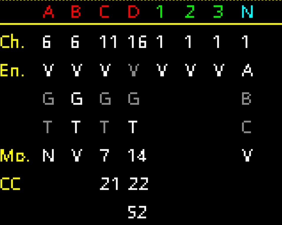
The main display of the psc at this point in time displays the configuration. So far, this has been the only useful use of the display at all.
Changing the configuration via SysEx is an awkward process, and inserting SysEx messages into PC sequencer software is not the most straightforward thing either. I did also write a standalone desktop app to produce the SysEx messages and send them over the USB serial link:
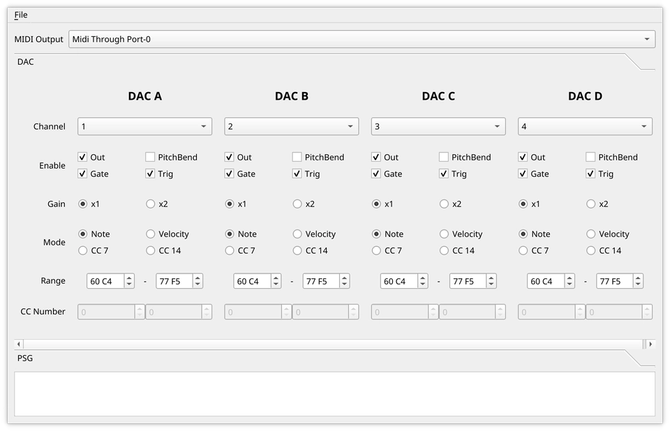
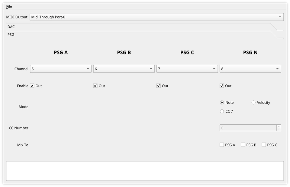
This doesn't lend itself to a smooth workflow, so it has stagnated at this level and I therefore don't generally change the configuration at all.
Second iteration
I felt that I was outgrowing the ESP8266 a bit in this application. ESP32 devices became available and I made a board revision to take the new microcontroller. However, every other aspect of the system remained the same.
It was my hope that the ESP32 could implement a proper USB MIDI device, but this never materialised. I was still constrained to be sending MIDI over the USB serial interface.
Third iteration
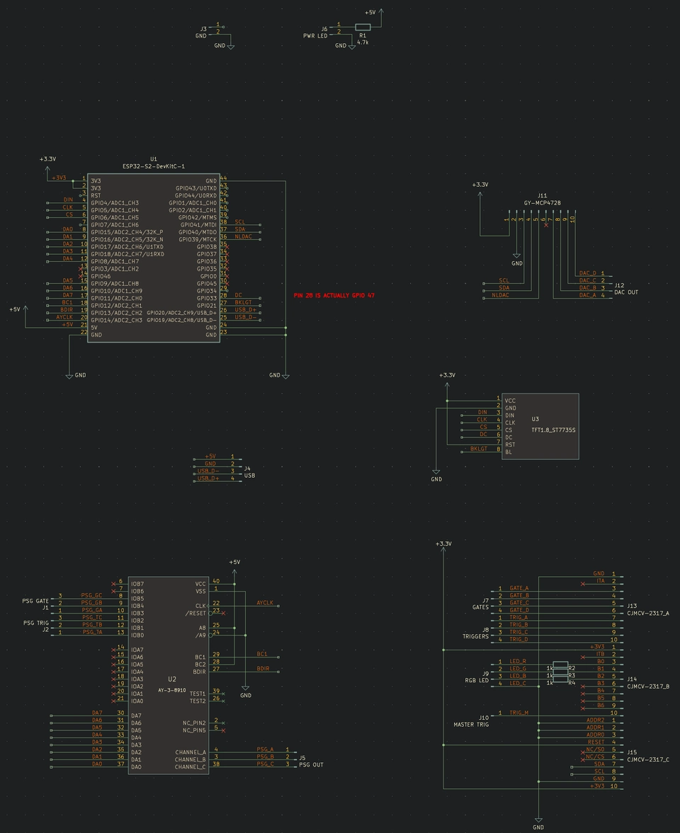
Some time later, the ESP32-S3 chips became available and these promised to implement proper USB MIDI. So, the third and current revision of the psc uses one.
Fortunately also, the ESP32-S3 also has enough GPIO pins to directly connect all of the other hardware peripherals, so I was able to get rid of the Arduino:
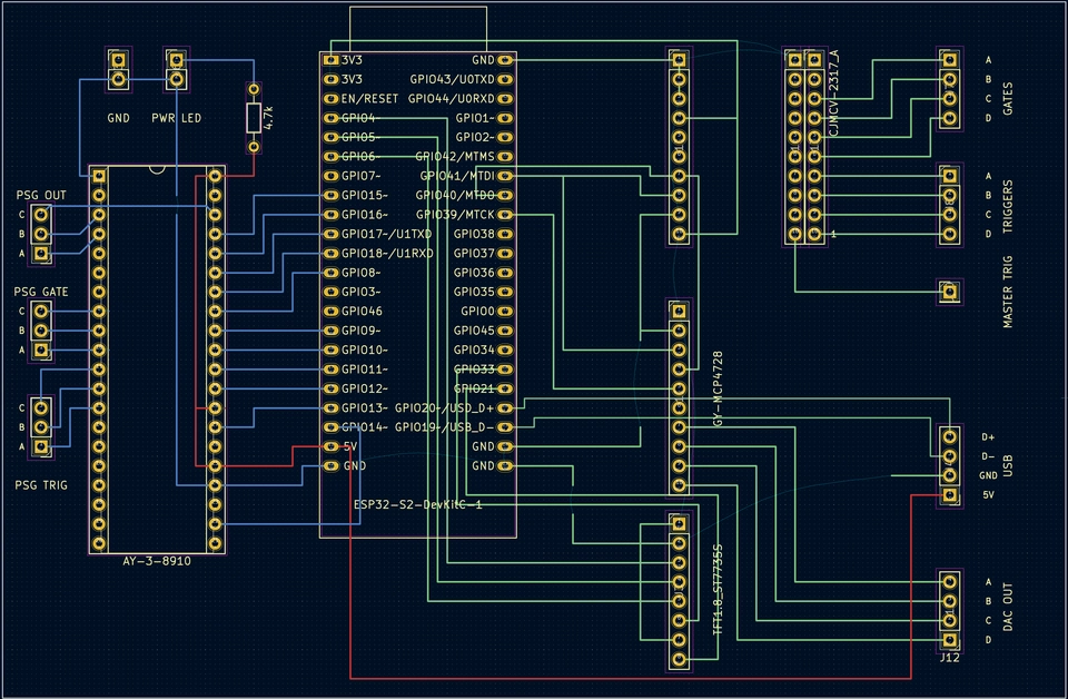
The "PCB" layout here is not exactly complete since I don't intend to actually get a PCB made; this drawing is only to facilitate a one-off hand build circuit on a prototyping board.
This simplifies the firmware a bit as well, I ported the AY register management code to a simple mapper class and that now runs directly in the ESP32-S3. Also in this process I ported the entire firmware to ESP-IDF instead of PlatformIO Espressif32 Arduino. This was necessary in order to get the USB interfaces working.
Finally though, this still requires the SysEx configuration protocol, but again, I still have just left it at the defaults and it's been working just fine so far.
This does however properly fulfil the original requirements that the psc should be plug-and-play MIDI device available on the PC. I can now plug it in via USB and use it directly with no further supporting software or protocol bridges.
This iteration's firmware code is here and the hardware design is here.
Evolution of the psc
One aspect of this device that I actually really enjoy is getting to use the vintage AY chip as a synth in its own right. I recently found a listing to buy some more of these chips from a well known Chinese marketplace website. The listing was apparently for 10 AY-3-8910 chips for £7. I thought that was worth a punt, despite the risk that I would be sent fake or relabelled chips that are not in fact the AY that I wanted. I added these to my next order and awaited to see what arrived.
To my surprise, the chips are legit! So, I am now planning a new device build using lessons learned from this project. This will be another ESP32-S3 controlling the following:
- 4x AY-3-8910
- 2x 8-channel DACs
- 1x 1.8" TFT LCD display
- 12x VCF circuits
- 3x touch pad inputs
All of these can be run from the ESP32-S3 GPIO pins without any expanders. There is a way to control an AY chip using only the 8-bit bus and just 1 other control line.
Because each AY chip has 3 oscillators on board, I think it would be fun to have a voltage controlled filter for each. This would make a 12 voice polyphonic chip-tune synth. I've got some of the initial design already done and partially prototyped on a breadboard, but for the moment I am not allowing myself to develop this further until I have completed a little bit of project backlog, including writing these blog posts for things I've built over the past few years. There's probably at least one more post to be written before I continue with this new synth.
Details of this build will be documented as I go here.
Wait a sec, what did I learn exactly?
It is clear that I couldn't end up achieving everything I wanted on the original list of requirements. In fact, some of the requirements (e.g. autonomous playing) were seriously complicated to implement, and at the same time extremely hard to even use.
It is unfortunate that I had to wait for the release of the ESP32-S3 to get USB MIDI working, but perhaps also I should not have been so hung up on using ESP devices at all (though I am a big fan of them), I could have found another microcontroller much earlier on that implements this reliably?
Some aspects of the device remain unfinished as well; the configuration management and the usage of the display and RGB LED are under-developed, but as previously mentioned there is just enough there to be able to get on and use the thing. After all, if the device is perpetually in development, at what point exactly am I going to get to use it? There is also the case that using the device informs development - it's quite hard to specify, design and implement something without validating requirements in some way. It would have been better perhaps throughout to have a much tighter design-use-amend feedback loop.