Fourays: A Tribute to the AY-3-8910
Table of contents
- What is the AY-3-8910?
- Limitations of the AY
- The multi-chip chip-tune synth
- Setting Design Goals
- ESP32-S3 Firmware
- Signals
- Units
- Unit Compatibility Issues
- PCB Design
- Assembly and Hardware Design
- If you feel like helping ?
UPDATE: this post was originally much shorter and published as "Part 1" on 30 Jan 2024, but I've since (10 Feb 2024) added more content to match the current state of the project as a whole. Further progress on this project will be made as new posts however.
UPDATE: 18 & 19 Feb 2024: I tested all of the AY chips.
What is the AY-3-8910?
I'm quite a fan of the old AY-3-8910 synthesizer chip. I've used one before in the psc, but wondered what a fully AY-only synth might be like.
I only had 2 of these chips until recently, one for the psc and another ... spare? I didn't want to disassemble the psc to make the next project so looked at acquiring some more. I found a listing on AliExpress for a lot of 10 for just £7. I wasn't sure if this was a legitimate listing, but decided the reasonable price was worth a gamble. A while later, a package arrived from China and inside was 10 chips correctly labelled as AY-3-8910.
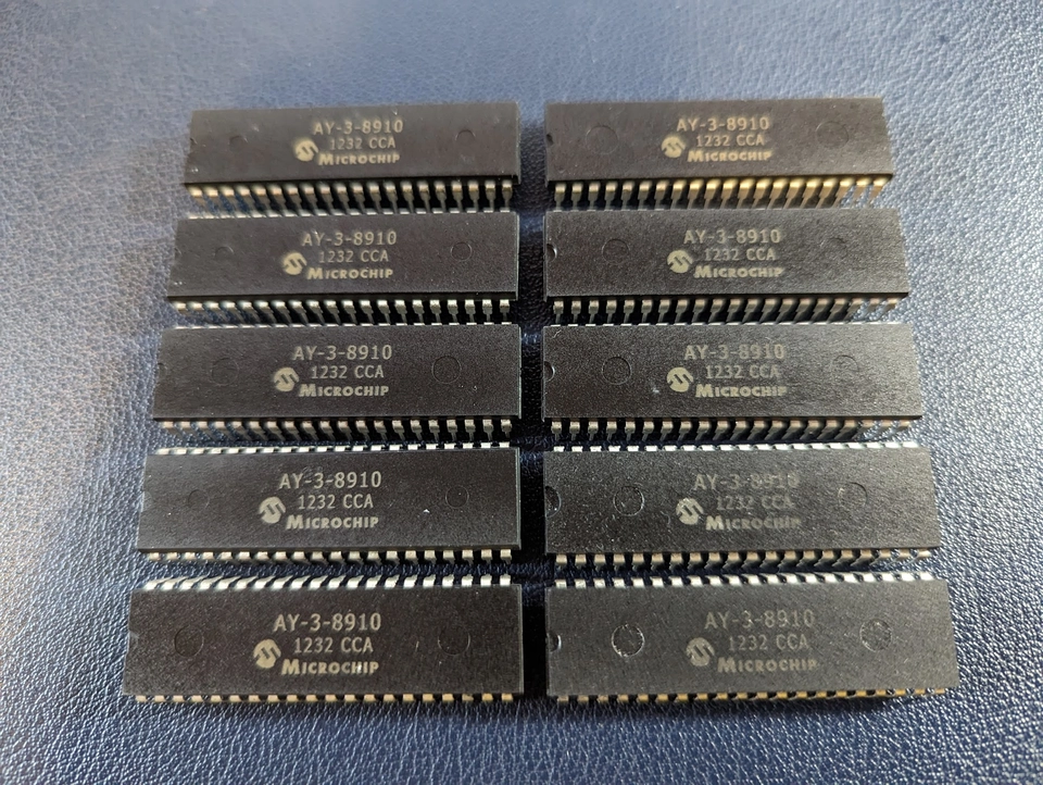
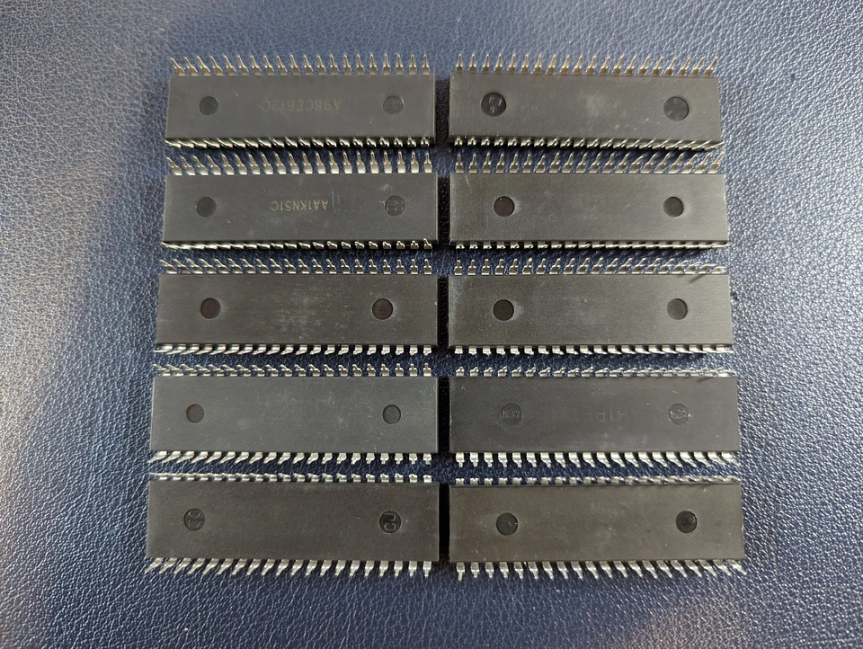
This was a nice start, but I still wasn't convinced that these were real chips as they look very clean and new and I was sure these chips haven't been manufactured for a long while. These chips also all look somewhat different from each other. The print markings quality varies and the mouldings and markings on the undersides differ as well.
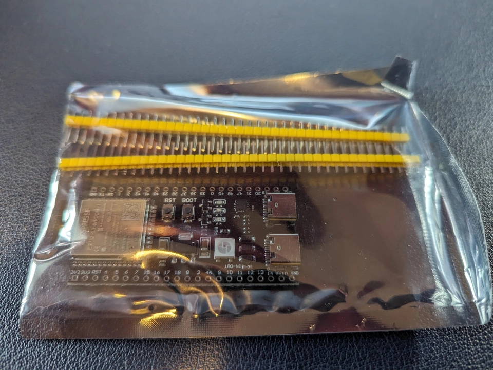
So, I picked the first chip off the stack, rigged up a clone of the psc code with another ESP32-S3, hooked up the control lines and waited to see if the chip actually behaved like an AY. It turns out at least two of them are totally real but I haven't tested all of them yet. So, we are good to go with planning an entirely AY synthesizer with at least 2 chips.
UPDATE 19 Feb 2024: I've revised my testing and have some more details about the chips here.
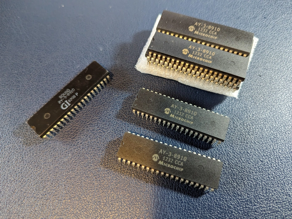
By comparison here's the new chips next to one of my old vintage ones, marked GI for General Instruments:
Limitations of the AY
The AY chips produce only square waves. This is a good start for chip-tune vibes but I think this synth could do with a bit more flavour. For my analogue synth I have built some Voltage Controlled Filters and like how they can modify the AY sound, so I think we could make some more VCFs and maybe have one per AY output.
Each AY has 3 oscillators and a noise generator; but it has only 3 audio outputs. Each oscillator is allocated to its own output, but the noise generator can be mixed into any or all of the outputs. So, we don't have as much control over the noise generator as we do the oscillators, but I think we can work with that. I think we should mix all of the audio outputs together into 1 or 2 outputs for the synth anyway.
The multi-chip chip-tune synth
Three oscillators is nice, but because I have loads of these chips now, it begs the question of exactly how many can be made to work together. Each AY chip requires the following input signals:
- 1x clock
- 8x data lines
- 1x bus direction line
- 1x bus control line
It turns out that for multiple chips under the control of the same microcontroller, the clock, data lines, and bus direction line can be shared to all of the chips. Only the bus control line is unique per chip and acts like a traditional chip select line. So, the total number of microcontroller outputs we need for N AY chips is 10 + N.
With the idea of a filter per audio output, we will also need control voltages for each filter. We therefore need 3N control analogue voltages. Most microcontrollers don't have very many usable DAC outputs, and usually they are quite low resolution, so we will probably need some dedicated DAC devices attached to the microcontroller. I've settled on using AD5328 devices. These use a 3-wire SPI interface but provide 8 analogue voltages each with 12-bit resolution. Each additional DAC requires only one more chip select signal from the microcontroller.
With the ESP32-S3 microcontroller acting as a USB device, it has 24 other usable output pins.
So, lets see how many microcontroller pins we need for some N of AY chips:
| N | AY control pins | Audio outputs/ VCFs | DACs | DAC control pins | TOTAL pins |
|---|---|---|---|---|---|
| 1 | 11 | 3 | 1 | 3 | 14 |
| 2 | 12 | 6 | 1 | 3 | 15 |
| 3 | 13 | 9 | 2 | 4 | 17 |
| 4 | 14 | 12 | 2 | 4 | 18 |
| 5 | 15 | 15 | 2 | 4 | 19 |
| 6 | 16 | 18 | 3 | 5 | 21 |
| 7 | 17 | 21 | 3 | 5 | 22 |
| 8 | 18 | 24 | 3 | 5 | 23 |
OK, so we could hook up 8 AY chips for a total of 24 oscillators and 8 noise generators and 24 VCFs. That's a tempting idea, but that's perhaps too many and leaves no scope for additional I/O on the microcontroller.
I like the idea of having a little screen for configuration and status display, and we also will need some touch or button inputs to control the user interface. I will use the same ST7735s type screen as I used for the psc and this shares the SPI bus with the DACs, but needs 3 additional control lines. For user interface inputs, I think we need a minimum of 3 touch or button inputs. That's a total of 6 more pins for user interface. If we subtract that from the 24 available, that leaves 18 remaining for the audio circuits.
So, we are able to use 4 AYs ... four AYs ... Fourays ... FOURAYS!
And with that, we will have used every usable pin on the ESP32-S3 and found a name for the project!
Microcontroller hookup
And with that lets start allocating pins on the ESP32-S3:
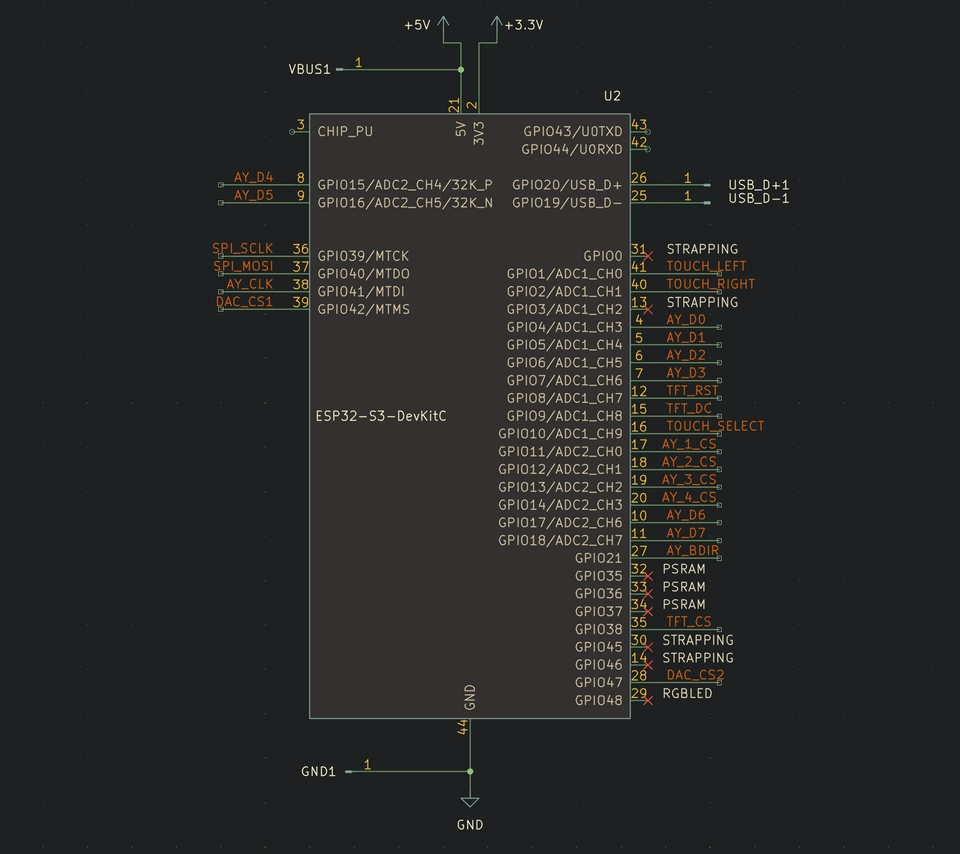
NOTE: Pin assignments have changed since this article was written, you should refer to the official Fourays documentation or repository for current references.
This consists of:
- 3x touch inputs
- 8x AY data bus lines
- 1x AY clock
- 1x AY bus direction line
- 4x AY bus control / chip select lines
- 2x SPI bus lines (clock & data)
- 2x DAC chip select lines
- 3x screen control lines
- 2x USB data lines
There are technically 8 more pins exposed, but for various reasons we cannot use these. Four influence the ESP startup ("strapping") and these are best avoided. Three interface with a built in peripheral, the PSRAM. The last one interfaces with an on-board RGB LED, which we don't need.
It should be noted as well that these pin choices are not arbitrary, this image comes from the future relative to this introductory post, having already tested and established which pins suit which functions. For example the touch inputs are only available on the first 14 GPIOs.
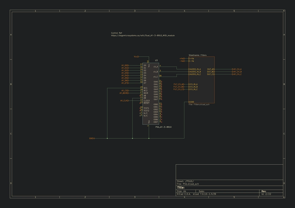
AY hookup
The AY chips were originally designed to be used with 11 control lines and 1 clock signal. However, it has been established that fewer than that is strictly necessary. I've used one reduced pin scheme in the psc design, but I've found a different one to use here, which saves another pin. I got this info from dogemicrosystems.
Each AY chip hookup therefore looks like this:
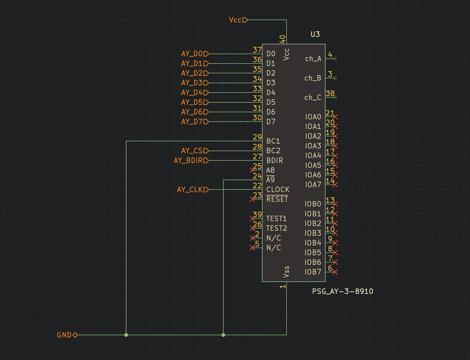
One thing I haven't mentioned yet is that each AY also has two 8-bit GPIO ports incorporated. I haven't made use of these in the design so far, but it could be considered as an alternative way to control the filters if we run into limitations with the microcontroller or DACs.
By setting these GPIO as outputs, we could implement an R-2R resistor ladder DAC. If we want high precision we would have to sacrifice the number of VCFs, perhaps have one per AY chip instead of one per audio output, or we could divide the GPIOs into multiple DACs with lower resolution. If we want to maintain one VCF per audio output, we'd only have 5 bits available per VCF control voltage, reducing the resolution quite significantly (65536 levels to just 32 levels).
Actually, driving the VCF control voltages from the AY itself would have the small advantage of ensuring that filter changes happen much closer in time as the note changes on the audio outputs, since the microcontroller would be setting both of these over the same bus in quick succession. I don't think the timing alignment will be as good using DAC devices, however I expect in practice the timing differences will not be audible at all, because we can drive either bus at MHz frequencies.
If I don't use these GPIOs for anything else, I might just hook up some LEDs as blinkenlights.
One final thing to note is that although the AY is specified as requiring a 5 volt supply, I have been able to power it successfully from the ESP32-S3 3.3 volt supply and it still outputs tones and at the correct frequencies. So, that should simplify the power requirements for the synth as well.
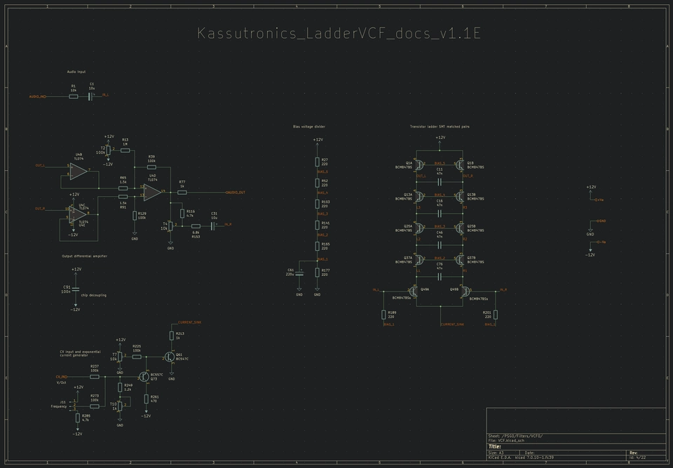
VCF filter design
The final circuit type to consider in this synth is the voltage controlled filter. I have simply lifted someone else's design for this, namely the kassutronics transistor ladder filter. This design is very close to the YuSynth Minimoog VCF which I made before for my analogue synth. I like the sound of that filter, but the kassutronics version has the advantage of not requiring CA3046 chips which are no longer available.
Setting Design Goals
I think all of the above makes a sensible plan for a synthesizer. We will be able to:
- use the ESP32-S3 as a USB MIDI device
- map MIDI channels/notes to AY oscillators
- map MIDI CC controllers to filter cut-off frequencies
We can mix the audio voices together and configure the synth to have either 1 output for mono or 2 outputs for stereo. We can decide later on the MIDI configuration and audio mixing strategy though.
ESP32-S3 Firmware
In order to have full control over the ESP32-S3 as a USB device, I am going to use ESP-IDF framework.
The firmware will be structured into several units which are mostly loosely coupled:
board: just a bunch of constants which define the peripheral pinouts.usb: initialises the USB interface, device descriptors.midi: initialises a MIDI interface which consists of bridging the ESP-IDF USB MIDI low level API to a MIDI packet interpreter. Exposes a set ofsignalobjects which can be observed for different MIDI message types.config: describes how to map MIDI messages to device peripherals, and an API to change these mappings.touch: watches the touch input pins and exposes a touchsignalwhen touch events occur.ay: AY-3-8910 device driver.dac: DAC device driver.tft: LCD screen graphics rendering functions.
Signals
I'm able to loosely couple most of these units using the signal pattern. A Signal is an object which can be observed and which can be called upon to emit events.
#include <signals.h>

Signal<> demoSignal;

void onSignal_1() {}
void onSignal_2() {}

int main() {
  demoSignal.emit(); // No observers, nothing happens

  demoSignal.connect(onSignal_1); // Registered one callback for the signal

  demoSignal.emit(); // onSignal_1 is called

  demoSignal.connect(onSignal_2); // Registered another callback for the signal

  demoSignal.emit(); // onSignal_1 and onSignal_2 are called

  return 0;
}
Units
Lets look at some of the units in a bit more detail. But first, what do I mean by "unit"? Practically speaking each unit so far is just a pair of .h/.cpp files (literally a C++ translation unit). Inside each unit I encapsulate the interface into a namespace. Most units expose a setup() function and perhaps some signals.
example-unit.h
namespace fourays::example
{
  Signal<> &exampleSignalGetter();

  void setup();
}
example-unit.cpp
#include "example-unit.h"

namespace fourays::example
{
  Signal<> s_example;

  Signal<> &exampleSignalGetter()
  {
    return s_example;
  }

  void setup()
  {
    // do some setup for example
  }
}
Note that in the descriptions of the following units I am by no means showing all of the code required, but it's worth showing some of the important parts which give the units their core functionality. A link to the actual code repo for fourays firmware will be published as open source in due course, once I've got all these units working nicely together (more on this later).
Unit: usb
This is a minor unit which initialises the tinyusb stack with my own device descriptor information and to initialise the USB configuration as a MIDI device.
#include <tinyusb.h>

#include "fourays-usb.h"

namespace fourays::usb
{
    /** TinyUSB descriptors **/

    // Interface counter
    enum interface_count
    {
#if CFG_TUD_MIDI
        ITF_NUM_MIDI = 0,
        ITF_NUM_MIDI_STREAMING,
#endif
        ITF_COUNT
    };

    // USB Endpoint numbers
    enum usb_endpoints
    {
        // Available USB Endpoints: 5 IN/OUT EPs and 1 IN EP
        EP_EMPTY = 0,
#if CFG_TUD_MIDI
        EPNUM_MIDI,
#endif
    };

#define TUSB_DESCRIPTOR_TOTAL_LEN (TUD_CONFIG_DESC_LEN + CFG_TUD_MIDI * TUD_MIDI_DESC_LEN)

    /**
     * @brief String descriptor
     */
    static const char *s_str_desc[5] = {
        // array of pointer to string descriptors
        (char[]){0x09, 0x04}, // 0: is supported language is English (0x0409)
        "lon.dev",            // 1: Manufacturer
        "fourays",            // 2: Product
        "123456",             // 3: Serials, should use chip ID
        "fourays",            // 4: MIDI
    };

    /**
     * @brief Configuration descriptor
     *
     * This is a simple configuration descriptor that defines 1 configuration and a MIDI interface
     */
    static const uint8_t s_midi_cfg_desc[] = {
        // Configuration number, interface count, string index, total length, attribute, power in mA
        TUD_CONFIG_DESCRIPTOR(1, ITF_COUNT, 0, TUSB_DESCRIPTOR_TOTAL_LEN, 0, 100),

        // Interface number, string index, EP Out & EP In address, EP size
        TUD_MIDI_DESCRIPTOR(ITF_NUM_MIDI, 4, EPNUM_MIDI, (0x80 | EPNUM_MIDI), 64),
    };

    void setup()
    {
        tinyusb_config_t const tusb_cfg = {
            .device_descriptor = NULL, // If device_descriptor is NULL, tinyusb_driver_install() will use Kconfig
            .string_descriptor = s_str_desc,
            .string_descriptor_count = sizeof(s_str_desc) / sizeof(s_str_desc[0]),
            .external_phy = false,
            .configuration_descriptor = s_midi_cfg_desc,
            .self_powered = false,
            .vbus_monitor_io = -1,
        };
        ESP_ERROR_CHECK(tinyusb_driver_install(&tusb_cfg));
    }
}
It seems like it is possible to define multiple distinct MIDI interfaces in the USB configuration should we need to, however for now I think we only need one and I also cannot find any way to know which interface received which data when we want to read it later on.
Unit: midi
In this unit I have wrapped the Arduino MIDI Library. This library is actually not Arduino framework specific, but is templated to allow integrating with components of other frameworks. In particular, we need to provide an implementation for something called Transport and something called a Platform.
template<class Transport, class _Settings = DefaultSettings, class _Platform = DefaultPlatform>
class MidiInterface
{
// --- snip ---
The Transport implements the interface to read and write data to the physical interface, that is to say the tinyusb USB MIDI interface:
#include <tinyusb.h>

class TUSBTransport
{
public:
    void begin() {}

    unsigned available()
    {
        return tud_midi_available();
    }

    byte read()
    {
        uint8_t ch;
        return tud_midi_stream_read(&ch, 1) ? (int)ch : (-1);
    }

    bool beginTransmission(int val)
    {
        // nothing to do here
        return false;
    }

    void write(int val)
    {
        // nothing to do here
    }

    void endTransmission()
    {
        // nothing to do here
    }

public:
    bool thruActivated = false;
};
Platform for some reason just needs a method to get the current timestamp:
#include <esp_timer.h>

class ESPIDFPlatform
{
public:
    static unsigned long now()
    {
        return esp_timer_get_time() / 1000;
    }
};
Once we've got these defined, we can create our MIDI interface and use it as per the library documentation. I'm also using a FreeRTOS task to manage reading the MIDI data arriving and map it to some signals which this unit exposes.
namespace fourays::midi
{
  static TUSBTransport transport;
  static ::midi::MidiInterface<TUSBTransport, ::midi::DefaultSettings, ESPIDFPlatform> midi(transport);

  void midi_task_read(void *arg)
  {
      for (;;)
      {
          vTaskDelay(1);
          while (midi.read())
          {
              switch (midi.getType())
              {
              case ::midi::MidiType::Stop:
                  s_allNotesOff.emit();
                  break;
              case ::midi::MidiType::SystemReset:
                  s_allNotesOff.emit();
                  break;
              case ::midi::MidiType::NoteOn:
                  s_noteOn.emit(midi.getChannel(), midi.getData1(), midi.getData2());
                  break;
              case ::midi::MidiType::NoteOff:
                  s_noteOff.emit(midi.getChannel(), midi.getData1(), midi.getData2());
                  break;
              case ::midi::MidiType::ControlChange:
                  s_controlChange.emit(midi.getChannel(), midi.getData1(), midi.getData2());
                  break;
              default:
                  break;
              }
          }
      }
  }

  void setup()
  {
    midi.begin(MIDI_CHANNEL_OMNI);
    midi.turnThruOff();

    xTaskCreate(midi_task_read, "midi_task_read", 8 * 1024, NULL, 5, NULL);
  }
}
Unit: touch
I found a good reference implementation of using touch inputs in the ESP-IDF documentation here:
I've used this almost verbatim, except for redefining my own buttons array and what happens inside the read task where I emit a signal when an input is activated:
#define TOUCH_BUTTON_NUM 3

    const touch_pad_t button[TOUCH_BUTTON_NUM] = {
        TOUCH_LEFT,
        TOUCH_RIGHT,
        TOUCH_SELECT,
    };

// --- snip ---

    using TouchSignal = Signal<touch_pad_t>;
    TouchSignal s_touch;

    void touchsensor_read_task(void *pvParameter)
    {
// --- snip ---
            if (evt.intr_mask & TOUCH_PAD_INTR_MASK_ACTIVE)
            {
                s_touch.emit((touch_pad_t)evt.pad_num);
            }
// --- snip ---
    }
Unit: ay
The AY unit exposes a simple interface for writing register values to an AY device:
// Libs
#include <AY38910.h>

namespace fourays::ay
{

    void setup();
    void writeRegisters(const uint8_t cs, const AY38910::DataFrame frm);

}
The setup function initialises the output pins:
- clock: using the LEDC PWM clock generator.
- 8-bit bus: using Dedicated GPIO Bundle. The advantage of doing this is that we can then write an 8-bit unsigned int to the bundle and the hardware will map each bit to the output pins in the correct order in a single function call. I think that's pretty neat.
- BDIR and chip select pins: as regular GPIO outputs.
The writeRegisters function iterates over the DataFrame and writes each value to the corresponding AY register. The implementation of the dogemicrosystems addressing scheme looks like this:
    enum class BC2Control
    {
        INACTIVE = 0b00,
        WRITE = 0b11,
        LATCH = 0b10
    };

    void setControl(uint8_t bc2, BC2Control mode)
    {
        // BC2 must be changed before BDIR

        const auto bc2val = (uint8_t)mode & 0b01 ? 1 : 0;
        gpio_set_level((gpio_num_t)bc2, bc2val);

        const auto bdir = (uint8_t)mode & 0b10 ? 1 : 0;
        gpio_set_level((gpio_num_t)AY_BDIR, bdir);
    }

    void setData(unsigned char data)
    {
        dedic_gpio_bundle_write(portD, 0xFF, data);
    }

    void writeRegister(uint8_t cs, uint8_t reg, uint8_t value)
    {
        // Ref: https://dogemicrosystems.ca/wiki/Dual_AY-3-8910_MIDI_module#Code
        uint8_t bc2 = 0;
        switch (cs)
        {
        case 0:
            bc2 = AY_1_CS;
            break;
        case 1:
            bc2 = AY_2_CS;
            break;
        case 2:
            bc2 = AY_3_CS;
            break;
        case 3:
            bc2 = AY_4_CS;
            break;
        }

        // Inactive (BDIR BC2 BC1 0 0 0)
        setControl(bc2, BC2Control::INACTIVE); // BDIR, BC2

        // Set register address
        setData(reg);

        // BAR (Latch) (BDIR BC2 BC1 1 0 0)
        setControl(bc2, BC2Control::LATCH); // BDIR

        // Inactive (BDIR BC2 BC1 0 0 0)
        setControl(bc2, BC2Control::INACTIVE); // BDIR

        // Set register contents
        setData(value);

        // Write (BDIR BC2 BC1 1 1 0)
        setControl(bc2, BC2Control::WRITE); // BC2, BDIR

        // Inactive (BDIR BC2 BC1 0 0 0)
        setControl(bc2, BC2Control::INACTIVE); // BC2, BDIR
    }
What is not shown here is the AY38910 mapper class which exposes a MIDI like interface but internally just updates the register states. We will use this later to receive events from the MIDI unit and update the state to send out to the AY chips.
class AY38910
{
public:
  bool allOff();
  bool noteOn(const uint8_t channel, const uint8_t note, const uint8_t velocity);
  bool noteOff(const uint8_t channel);
  bool noiseOn(const uint8_t freq, const uint8_t output_mask);

// --- snip ---

private:
  DataFrame m_frame;
}
Unit: dac
I could not find any existing libraries for interfacing with the AD5382 DACs. It turns out though that this is pretty simple, we combine the DAC channel number with the data and write it out over the SPI bus. Remember that we have 2 DAC devices (via cs) each with 8 channels (via ch), for a total of 16 outputs, of which we need only 12.
namespace fourays::dac
{
    void writeDac(const int cs, const uint16_t data)
    {
        buf[0] = data >> 8;
        buf[1] = data & 0xFF;

        spi->mode(2);
        gpio_set_level((gpio_num_t)cs, 0); // /SYNC
        spi->beginTransaction();
        spi->writeBytes(buf, 2, false, true);
        spi->endTransaction();
        gpio_set_level((gpio_num_t)cs, 1); // /SYNC
    }

    void writeDacOutput(const int cs, const uint8_t ch, const uint16_t val)
    {
        // Page 16 "DAC Write" / Figure 34: Shift register contents
        // [RW, A2, A1, A0, d12...d0]
        // RW; 0=Write DAC value
        const uint16_t data = (ch << 12) | (val & 0xFFF);
        writeDac(cs, data);
    }
}
This works because in the setup we configure the DACs for "continuous update using SYNC" mode
namespace fourays::dac
{

    void setup(psc::io::SPI_sptr bus)
    {
        // Manage the control pins manually
        for (auto pin : cs_gpios)
        {
            gpio_set_level((gpio_num_t)pin, 1); // CS /SYNC is inverted

            // Page 18: Gain, BUF and Vdd config
            const uint16_t cfg = (1 << 15) | 0b00'00'11;
            writeDac(pin, cfg);

            // Table 8: /LDAC
            // /LDAC low mode; continuous update using SYNC;
            // /LDAC must be tied high
            const uint16_t ldacmode = (1 << 15) | (1 << 13) | 0x00;
            writeDac(pin, ldacmode);
        }
    }
}
Unit: tft
This unit initialises the SPI bus, and provides a function to display the MIDI mapping configuration on the screen. I have done this so far using the LovyanGFX library. I really like this library for a few reasons:
- The API is very straightforward and mimics the TFT_eSPI library I have used before in the
psc. I therefore was able to start the configuration rendering implementation mostly by copying what I'd already written forpsc. - It seems to configure the TFT LCD for good colour contrast and clarity. I have seen other libraries using different screen initialisation commands which ends up making the graphics look fuzzy and/or washed out.
- Its SPI interface is fast. Really fast. I'm not sure what it does to achieve this (and we'll read later more about this), but other libraries don't seem to be able to do full screen updates anywhere near as fast as this library.
The long list of graphics API calls for rendering the configuration isn't particularly enlightening to read, so I'll skip showing any code for this unit.
main
To stitch all of the above together, we need to create an instance of each unit, call their setup functions and then start connecting signals:
using namespace fourays;

namespace state
{
    static config::Config cfg;
    static dac::DACState dac;
}

extern "C" void app_main(void)
{
    usb::setup();
    midi::setup();

    ay::setup();

    dac::setup(io::SPI());
    tft::setup(io::SPI());

    midi::allNotesOff().connect(handleAllNotesOff);
    midi::noteOn().connect(handleNoteOn);
    midi::noteOff().connect(handleNoteOff);
    midi::controlChange().connect(handleControlChange);

    auto controller = state::cfg.controller();
    touch::touch().connect(
        [](const touch_pad_t &pad)
        {
            switch (pad)
            {
            case TOUCH_LEFT:
                controller->next({.type = State::ControlEventType::LEFT});
                break;
            case TOUCH_RIGHT:
                controller->next({.type = State::ControlEventType::RIGHT});
                break;
            case TOUCH_SELECT:
                controller->next({.type = State::ControlEventType::SELECT});
                break;

            default:
                break;
            }
        });
    touch::setup();

    state::cfg.changed().connect(
        []()
        {
            tft::displayConfig(state::cfg);
        });
    controller->navigate().connect(
        []()
        {
            tft::displayConfig(state::cfg);
        });

    config::setup();
    state::cfg.load("default");
}
The various handle* functions not shown here use the cfg to find out where to route the data and may eventually end up calling a dac::update or ay::writeRegisters.
I also haven't described what the config controller is. That is worthy of its own article, and I will follow up with more details on that.
Unit Compatibility Issues
As it stands right now, each unit on its own works perfectly well. But there is a major problem I am still trying to solve. This revolves around the fact that the DAC and TFT share an SPI bus.
I have established the following all works:
- Using DAC on its own works perfectly
- Using the display on its own works perfectly
- Using the DAC and then the display, both work
- Using the display and then the DAC - the display is updated, but the DAC stops responding to any further commands
I've tracked this down to the fact that whatever LovyanGFX is doing to make the SPI writes to the display so fast is very specific to writing to a single TFT device on the bus. The library expects no other devices will be using the bus, which kind of makes it not-a-bus. When the next DAC write occurs, the bus has been reconfigured into a state or mode which the DACs do not understand and therefore they no longer update.
I have raised this as an issue with LovyanGFX (#491) but I am still not convinced the author understands the issue and I have little hope that it'll be resolved any time soon.
There's probably three ways I can go from here:
- Find another graphics library which doesn't mess around with the SPI bus so much. I would consider this a cop-out though, as I'm not keen on losing the display refresh performance nor the familiar graphics API.
- See if I can assign the DAC and TFT to different SPI busses, but I am technically out of available pins to use, and I'll need two more. I will need to do some further tests to see if I can use any of the "unavailable" pins. For example, using a "strapping" pin should be fine as long as I initialise and use it well after the ESP has started up. This glosses over the issues with the graphics library at the expense of more hardware complexity.
- Attach a logic analyser to the bus and find out what is being sent to the DACs before and after the display has been used. There's a chance with this method I can find out what has changed and trace down the code which has made that change, and possibly then reverse that when the DAC is used. This therefore would perhaps benefit not only myself but everyone else wanting to use this graphics library.
1. Alternative Graphics Libraries
I've done a fair amount of searching for libraries to use already, prior to integrating LovyanGFX. There's not a lot to choose from. Most libraries which turn up in results assume you are using the Arduino framework, which I am not because it lacks decent support for using the ESP32-S3 as a USB device. Other libraries or examples I have found are for similar displays using interfaces which are not SPI.
- LVGL - looks very flashy but ESP32 support is very limited. The documentation is actually very sparse and lot of links on the website don't work or lead to 404s. When I did eventually get it to "work", the performance was terrible and the screen colours incorrect. I gave up trying to fix it.
- nopnop2002/esp-idf-ili9340 - finding out that the ST7735s is mostly compatible with ILI9340 was news to me. This actually works but I had to make a few minor fixes. Performance is not great though and the initialisation commands make the display look kinda fuzzy. I couldn't get the initialisation commands from other libraries to work in this one.
- Official espressif ili9341 driver - I haven't tried this one yet, I didn't know initially that this could be compatible with my ST7735s device.
2. Split the SPI busses
I'm not sure why I didn't think of this before I started writing this article, perhaps I was too hung up on which ESP32-S3 pins should never be touched. However, less than one hour hacking proves this to actually work. Fortunately as well the ESP32-S3 has another available SPI host driver. So, we'll use SPI2_HOST on one set of pins for the TFT and SPI3_HOST with another set of pins for the DACs. At the moment I am still using the LovyanGFX SPI driver even for the DACs, as I assume I will get the same advantage of SPI speed/efficiency that it implements, even though I have no idea how to measure that efficiency and test that hypothesis at the moment.
diff --git a/esp32-s3-idf/src/psc-dac.cpp b/esp32-s3-idf/src/psc-dac.cpp
index b7d13dc..de92022 100644
--- a/esp32-s3-idf/src/psc-dac.cpp
+++ b/esp32-s3-idf/src/psc-dac.cpp
@@ -44,6 +44,10 @@ namespace psc::dac
         writeDac(idx, data);
     }

+    psc::io::SPI_sptr bus = std::make_shared<psc::io::PSCSPI>(
+        SPI3_HOST, SPI_DAC_SCLK, SPI_DAC_MOSI, SPI_DAC_MISO, -1,
+        2, SPI_MASTER_FREQ_8M);
+
     void setup()
     {
         gpio_config_t io_cs_conf = {
@@ -70,7 +74,7 @@ namespace psc::dac
             .spics_io_num = DAC_1_CS,
             .queue_size = 1,
         };
-        ret = spi_bus_add_device(SPI2_HOST, &devcfg0, &dacs[0]);
+        ret = spi_bus_add_device(bus->config().spi_host, &devcfg0, &dacs[0]);
         ESP_ERROR_CHECK(ret);

         spi_device_interface_config_t devcfg1 = {
@@ -79,7 +83,7 @@ namespace psc::dac
             .spics_io_num = DAC_2_CS,
             .queue_size = 1,
         };
-        ret = spi_bus_add_device(SPI2_HOST, &devcfg1, &dacs[1]);
+        ret = spi_bus_add_device(bus->config().spi_host, &devcfg1, &dacs[1]);
         ESP_ERROR_CHECK(ret);

         // -----
@@ -108,11 +112,13 @@ namespace psc::dac

     void beginTransaction(spi_device_handle_t dev)
     {
-        uint32_t spi_port = (SPI2_HOST + 1);
+        auto cfg = bus->config();
+
+        uint32_t spi_port = (cfg.spi_host + 1);
         (void)spi_port;
-        uint32_t clkdiv = lgfx::v1::FreqToClockDiv(lgfx::v1::getApbFrequency(), SPI_MASTER_FREQ_8M);
+        uint32_t clkdiv = lgfx::v1::FreqToClockDiv(lgfx::v1::getApbFrequency(), cfg.freq_write);

-        int spi_mode = 2;
+        int spi_mode = cfg.spi_mode;
         uint32_t user = SPI_USR_MOSI | SPI_USR_MISO | SPI_DOUTDIN;
         if (spi_mode == 1 || spi_mode == 2)
             user |= SPI_CK_OUT_EDGE;
@@ -147,8 +153,6 @@ namespace psc::dac
             return;
         }

diff --git a/esp32-s3-idf/src/psc-tft.cpp b/esp32-s3-idf/src/psc-tft.cpp
index 2539604..9fb0790 100644
--- a/esp32-s3-idf/src/psc-tft.cpp
+++ b/esp32-s3-idf/src/psc-tft.cpp
@@ -4,6 +4,8 @@

 #include <memory>

+#include <driver/spi_master.h>
+
 namespace psc::tft
 {
     std::shared_ptr<LGFX> display;
@@ -18,9 +20,12 @@ namespace psc::tft
     // Cols offset +4px for single char column centred
     constexpr uint8_t COLSC[] = {5, 22, 39, 56, 73, 90, 107, 124, 141, 158};

-    void setup(psc::io::SPI_sptr bus)
+    psc::io::SPI_sptr bus = std::make_shared<psc::io::PSCSPI>(
+        SPI2_HOST, SPI_TFT_SCLK, SPI_TFT_MOSI, SPI_TFT_MISO, TFT_DC,
+        0, SPI_MASTER_FREQ_40M);
+
+    void setup()
     {
         display = std::make_shared<LGFX>(bus);

         display->init();
diff --git a/esp32-s3-idf/src/psc-tft.h b/esp32-s3-idf/src/psc-tft.h
index 37cda32..7da7a3c 100644
--- a/esp32-s3-idf/src/psc-tft.h
+++ b/esp32-s3-idf/src/psc-tft.h
@@ -69,7 +69,7 @@ namespace psc::tft
         }
     };

-    void setup(psc::io::SPI_sptr bus);
+    void setup();
     void displayConfig(psc::config::Config &cfg);

 } // namespace psc::tft
3. Debug the SPI bus
Well it turns out for the time being I don't need to do this. I'll continue to build this project out using dual SPI busses for now.
PCB Design
Up to this point I have been prototyping this system entirely on breadboard. This test rig consists of two AY chips, one DAC and the TFT display. The DAC is hooked up to LEDs to check that the outputs are working.
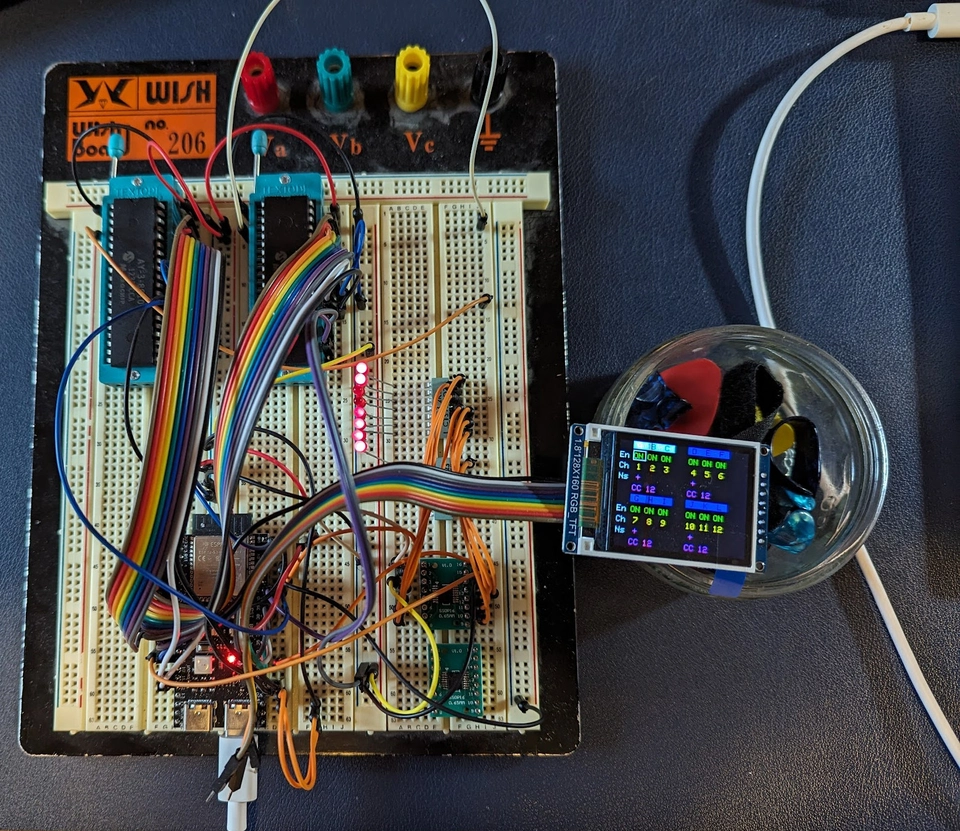
I have also in parallel been laying out the schematic and PCBs in KiCAD.
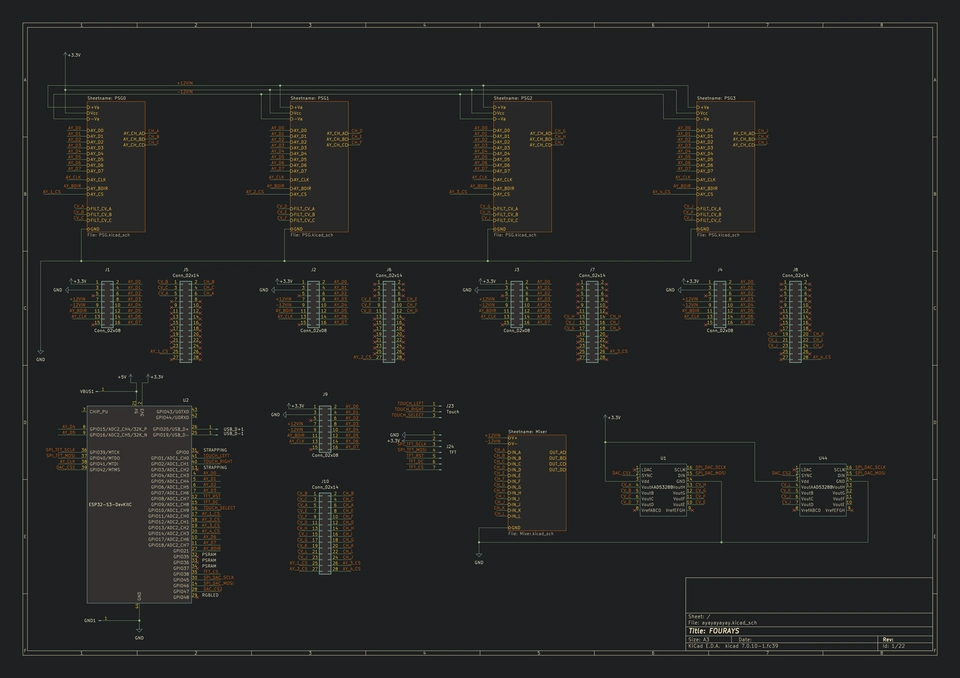
Top-level system hookup
AY chip hookup
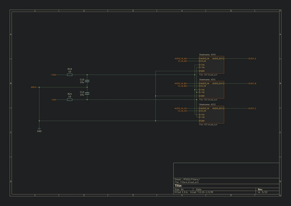
AY audio circuits
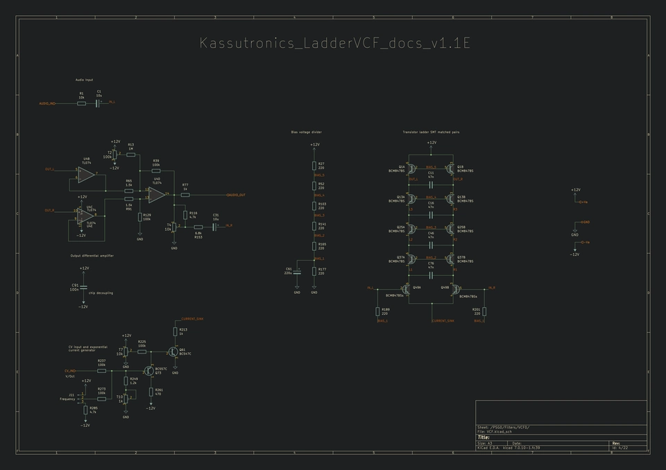
VCF filter
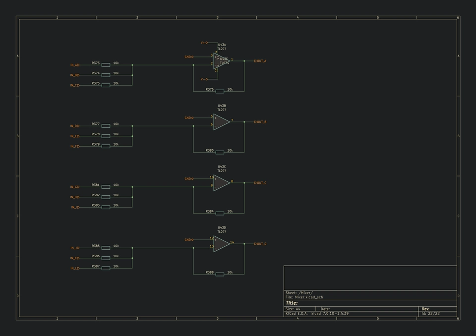
AY audio outputs mixer
For the PCB layout, I will place one AY and three VCF filters on one board, and therefore need four instances of these boards. I have routed all the AY and VCF ins and outs to bus connectors, but each board has breakout pads between the bus connector and the devices so that each AY and VCF can be connected to a different part of the bus.
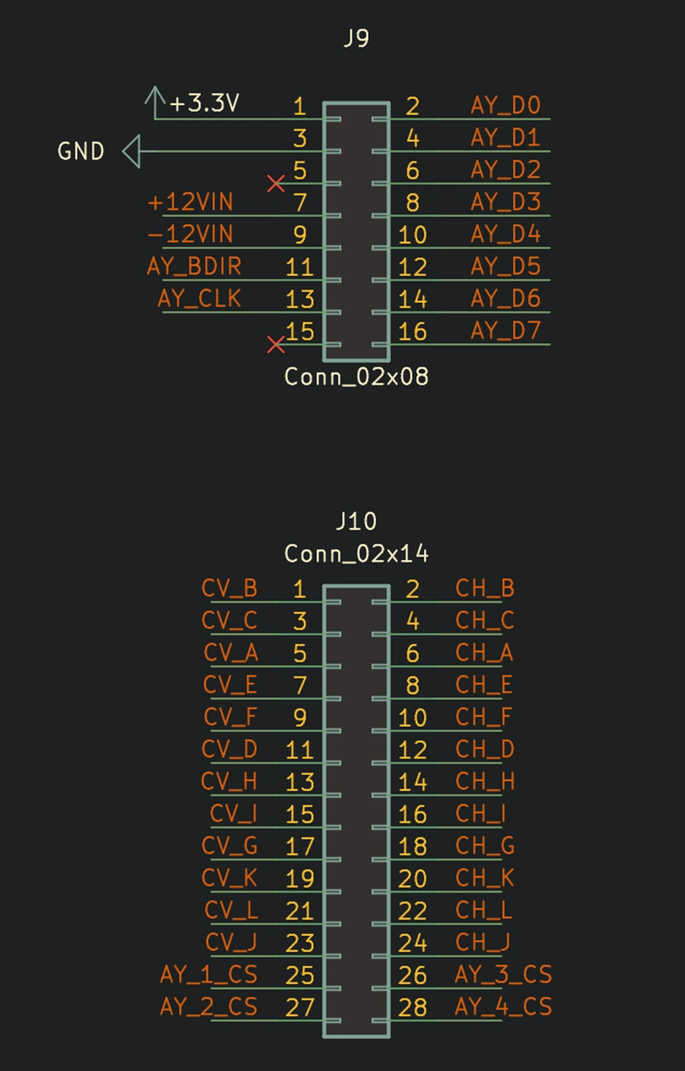
AY/VCF board bus connectors. The smaller connector is the shared AY control bus, the larger connector is the AY select and audio I/O bus.
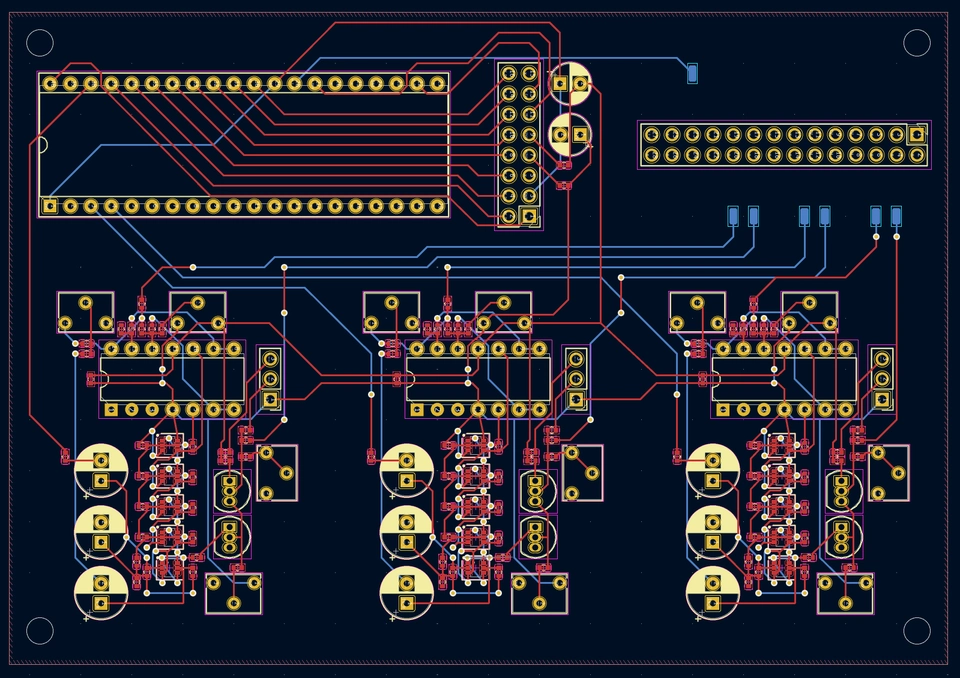
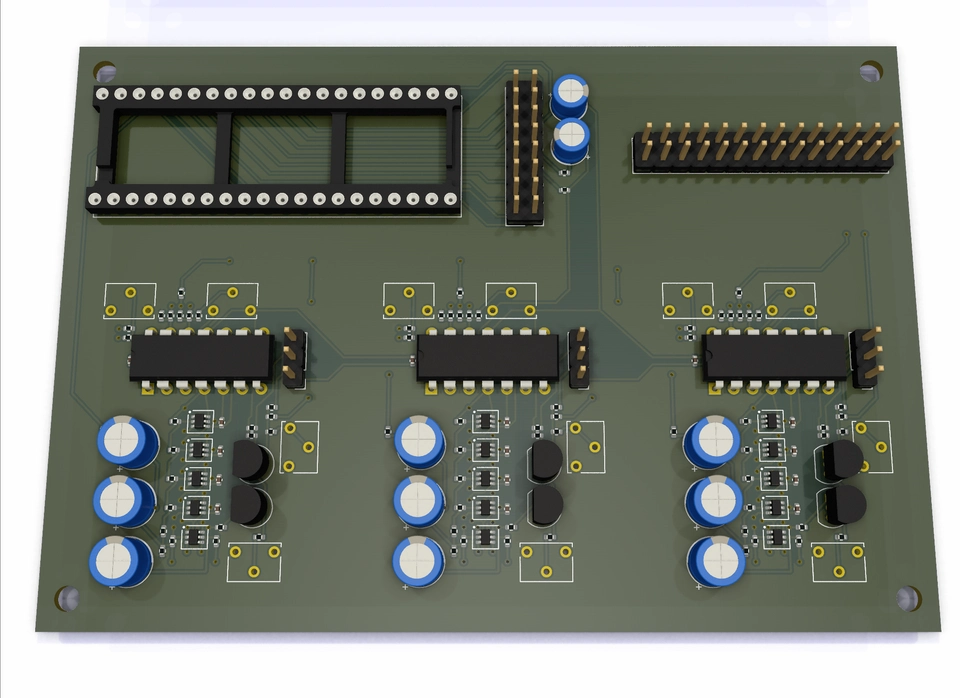
AY/VCF board layout and KiCAD 3D render
On each board I will have to manually connect each of the blue pads to the correct pins on the bus connectors. However, in this way it means that I can manufacture four identical boards.
The bus connectors are also present in the same location on a controller board, where every connection is routed to the appropriate ESP32-S3 pin or audio circuit.
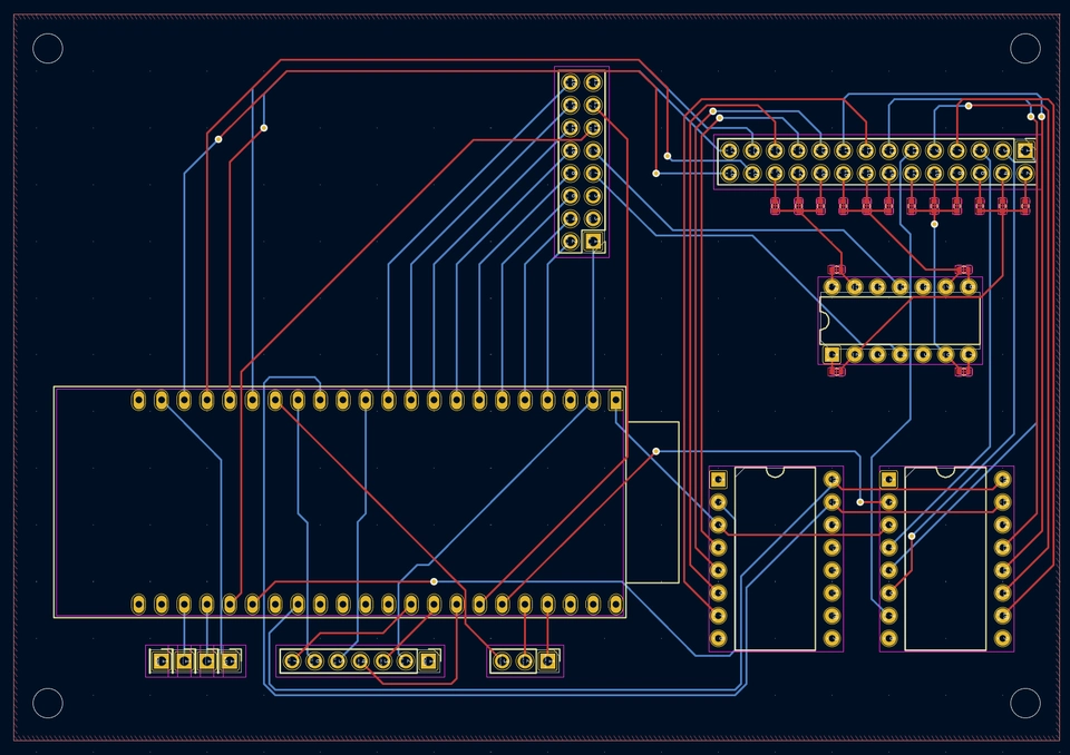
Controller board layout. The four devices on this board are the ESP32-S3, 2x AD5328 DACs, one op-amp audio mixer. The large connectors at the top are the board busses. The small pin headers on the bottom row are USB, TFT, Touch inputs respectively from left to right.
Assembly and Hardware Design
Overall dimensions
By placing all of the bus connectors in the same location on every board, it suggests that all of the boards can be assembled together in a vertical stack, rather than side by side. At this time though I have not figured out any of the physical assembly of this thing. However, my gut feeling is that both a five board stack or a five board flat layout will lead to this being quite a large device overall. A vertical stack will end up being a chunky cube of boards. The flat layout will take over 475 cm2 - equivalent to a square with 22 cm sides.
I/O and controls
The device ideally will be entirely USB bus powered, however I think I still need additional power for the audio mixer, as these devices typically run on +/- 12 volts, which is required to get enough headroom for the op-amps to do their thing. I'm not sure yet how to get that voltage, I most likely will need an external DC power supply and include some regulators as well. There's enough spare space on the controller board to include the power input and regulation.
The synth will have three touch input controls for adjusting the configuration. These will likely either be hidden under the case and indicated by painted or drawn markings on top, or I could expose some small metal pads or buttons which would probably make them both more visible and more reliable to use.
I could also provide some manual potentiometer controls for the filters. The filters' cut-off frequency is designed to be MIDI controlled, but these can be blended with manual controls as well. I have also allowed in the PCB design for the filter resonances to be either fixed by installing fixed resistors, or to be manually adjustable from potentiometers. A full set of manual filter controls then would consist of 24 potentiometers, which may be too many. I am not aware of any way to make the resonance MIDI controllable, even the filters I have built before for my analogue synth did not have CV control over resonance.
I will do some 3D render mocks for the assembly and see what looks good and also serves the practical purpose of the synth.
If you feel like helping ?
I am more than happy to try to complete this project with my own curiosity and determination, but I would also love to have some help on this - even if its just to drop a note about an idea you have or some comment which may be helpful to steer the project towards completion where there are still unanswered questions. Or if you've spotted bugs or issues in my firmware code by all means send a comment or PR.
The repository for Fourays including all the firmware, library code and KiCAD files is here:
The entire repository is GPL 3 licensed, so you are also free to use anything from this project in your own as long as you follow the terms of the license.