Fourays: Updating Firmware & Debating Hardware Design
Table of contents
Firmware
I've done quite a bit more work on the firmware now, and I believe it to be mostly functionally complete for producing music as I now have complete control over the AY chips. There is still some more work to do on the configuration management and screen user interface though.
AY Control
Up to this point not all of the AY's features have been made available via config or MIDI control. We had config control over the noise mixer, but to change this during performance using config is impractical, some other means would be better.
A common method to enable or disable synth features during a performance is to use MIDI key switches. These switches are normally mapped to the lowest MIDI notes, which are out of range of the instrument. Using this method, we can implement the remaining features of the AY chips in a way which can be controlled during performance. In this instance I'll use a Note On message with velocity > 63 to turn a feature on and a Note On message with a velocity < 64 to turn a feature off.
Envelope Generator
The AY's envelope generator has 3 mix switches, 4 mode switches and a period parameter. When enabled for an oscillator, that oscillator's level will be affected by the envelope generator according to its mode and period.
All 7 switches are mapped to MIDI key switches:
| MIDI Note Number | MIDI Note Name | Switch |
|---|---|---|
| 1 | C#-1 | Enable for oscillator A |
| 2 | D-1 | Enable for oscillator B |
| 3 | D#-1 | Enable for oscillator C |
| 4 | E-1 | Hold mode enable |
| 5 | F-1 | Alternate mode enable |
| 6 | F#-1 | Attack mode enable |
| 7 | G-1 | Continue mode enable |
The period is controlled by CC messages, and the CC can be changed in the configuration. However, the longest period is probably too long for practical purposes, so the CC range is currently hard-coded to be mapped to the lowest 20% of the period range.
The various modes can be combined to make the envelope generator behave in different ways:
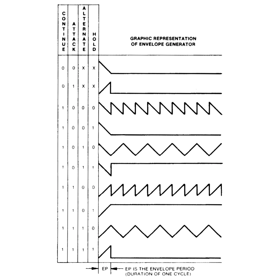
From the AY-3-8910 data sheet; Figure 1.
Noise Generator
The noise generator period is set via CC messages, and the CC for each noise generator can be set in the configuration. The noise mixer configurations have been moved to key switches.
MIDI key switch mapping:
| MIDI Note Number | MIDI Note Name | Switch |
|---|---|---|
| 8 | G#-1 | Mix to output A enable |
| 9 | A-1 | Mix to output B enable |
| 10 | A#-1 | Mix to output C enable |
Pitchbend, Transpose and Detune
Each MIDI note is mapped to an oscillator divisor value, which causes the oscillator to sound at something very close to the required note frequency.
The actual oscillator frequency is calculated as:
Frequency = Clock / 16 / Divisor
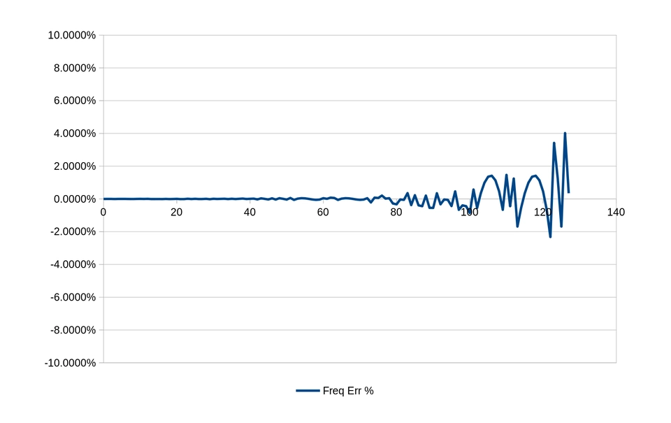
As such, it is not perfectly possible to match every note frequency across the entire MIDI note range because of the integer division.
We are driving the Clock at 2.0 MHz, which means that the lowest 23 MIDI notes are unplayable. This is because these notes would require a Divisor value greater than would fit in the 12-bit divisor control register (4095). The available Divisor resolution also decreases as the MIDI note increases, which causes the frequency error to also increase as we go up the scale. We peak at about 4% frequency error in the very highest notes, but nobody wants to listen to 5kHz square waves anyway.
To give the performer some control over the exact frequency output of the oscillators we can implement some CC messages to affect the frequency.
- Transpose: offsets the MIDI note in semi-tone increments. This is mainly so that if two oscillators are mapped to the same MIDI channel, then they can independently be transposed; this means we can implement octave doubling, for example.
- Pitchbend: we implement the standard MIDI pitch bend commands which smoothly adjusts the
Divisorbetween adjacent whole-tones. TheDivisordifference between any two adjacent notes is not constant across the note range, so we have a separate map ofDivisordeltas that we index into for applying pitch bend. - Detune: this value directly adds/subtracts from the
Divisorvalue itself.
The final Divisor is therefore calculated as:
Divisor = divisor_note_map[Note + Transpose] + (divisor_delta_map[Note + Transpose] * Pitchbend) + Detune
Polyphony
Using the Fourays synth with each oscillator mapped to different MIDI channels is cumbersome, and is not the way most MIDI music is written. It is more useful to be able to map multiple oscillators to the same MIDI channel write our music polyphonically, and have the firmware allocate Note On events to available oscillators.
This was surprisingly straightforward to achieve, given the event driven architecture of the firmware using signals. In the monophonic firmware, we connected the incoming MIDI Note On and Note Off messages for each channel directly to the oscillator control handler.
I'll illustrate this using simplified excerpts of the firmware C++ (ish) code. This code probably isn't strictly valid, I'm just trying to demonstrate the connections and the algorithm.
// Create two arrays of Note message signals, to cover all the MIDI channels.
Signal<int note, int velocity>[16] channel_signals_note_on;
Signal<int note, int velocity>[16] channel_signals_note_off;

// Re-configure all the oscillators
for (auto &oscillator : oscillators) {
    channel_signals_note_on[oscillator.config.channel].connect(
        [](note, velocity) {
            oscillator.note_on(note, velocity);
        }
    );
    channel_signals_note_off[oscillator.config.channel].connect(
        [](note, velocity) {
            oscillator.note_off(note, velocity);
        }
    );
}

// When we receive any MIDI Note On message, dispatch it to the correct channel
midi_input.note_on.connect(
    [](channel, note, velocity) {
        channel_signals_note_on[channel].emit(note, velocity);
    }
);

// When we receive any MIDI Note Off message, dispatch it to the correct channel
midi_input.note_off.connect(
    [](channel, note, velocity) {
        channel_signals_note_off[channel].emit(note, velocity);
    }
);
To implement polyphony, we need to upgrade the channel signals array to an array of some objects which know how many oscillators are available per channel and keeps track of which oscillators are playing which notes:
using NoteSlot = std::function<void(int note, int velocity)>;

// This object replaces the Channel signals,
// and now holds references to the oscillator control functions.
class ChannelManager
{
public:
    // Add the oscillator on/off handlers to this manager
    void connect(NoteSlot on_slot, NoteSlot off_slot)
    {
        m_slots.push_back({ .on=on_slot, .off=off_slot });
    }

    // Decide what to do with each incoming note on message;
    // Find an available oscillator and activate it.
    void note_on(int note, int velocity)
    {
        if (m_active_notes.contains(note))
        {
            return; // note is already on
        }

        // find an available slot
        for (size_t i = 0; i < m_slots.size(); ++i)
        {
            // if this slot is not in use
            if (!m_active_slots.contains(i))
            {
                m_active_slots[i] = note;      // allocate the oscillator
                m_active_notes[note] = i;      // allocate the note
                m_slots[i].on(note, velocity); // forward the note to the oscillator
                return;
            }
        }

        // If we reach here ... we can consider this later ...
    }

    // Decide what to do with each incoming note off message;
    // If an oscillator is playing the note then end it and make
    // both the oscillator and note available for use again.
    void note_off(int note, int velocity)
    {
        if (!m_active_notes.contains(note))
        {
            return; // note is not on
        }

        // find which oscillator is playing this note
        const auto i = m_active_notes[note];

        m_active_slots.erase(i);        // free the oscillator
        m_active_notes.erase(note);     // free the note
        m_slots[i].off(note, velocity); // forward the note to the oscillator
    }

private:
    // Array of available oscillator control functions
    std::vector<struct { NoteSlot on; NoteSlot off; }> m_slots;

    // Somewhere to keep track of which oscillators are in use;
    // Useful for when we want to turn a note on
    std::unordered_map<uint8_t, uint8_t> m_active_slots; // maps <slot index, note>

    // Somewhere to keep track of which notes are currently on;
    // Useful for when we want to turn a note off
    std::unordered_map<uint8_t, uint8_t> m_active_notes; // maps <note, slot index>
};

ChannelManager[16] channel_managers;

// Re-configure all the oscillators
for (auto &oscillator : oscillators) {
    channel_managers[oscillator.config.channel].connect(
        [](note, velocity) {
            oscillator.note_on(note, velocity);
        },
        [](note, velocity) {
            oscillator.note_off(note, velocity);
        }
    )
}

// When we receive any MIDI Note On message, dispatch it to the correct manager
midi_input.note_on.connect(
    [](channel, note, velocity) {
        channel_managers[channel].note_on(note, velocity);
    }
);

// When we receive any MIDI Note Off message, dispatch it to the correct manager
midi_input.note_off.connect(
    [](channel, note, velocity) {
        channel_managers[channel].note_off(note, velocity);
    }
);
All of the polyphony handling was done in the middle layer without changing either the MIDI input driver or the oscillator controllers.
There's further work we could do here as well, as indicated by the final comment in the ChannelManager::note_on method. At the moment, if there are not enough available oscillator slots for the next Note On message, then the message is ignored. We could however do something else. We could for example "steal" an oscillator and make it play the new note in place of some other note which was currently playing. There's quite a few different strategies we could employ to do this; either steal from the oldest or newest playing note, or the highest, or lowest, or something in the middle. I'm not going to implement any of these for the time being though.
Finally, I think I will need to add a polyphony on/off configuration somewhere, since it is at odds some of the other options available, particularly Transpose. By which I mean that if two AYs are on the same MIDI channel with polyphony enabled, you can just write your music in octaves, you don't need to transpose one of the oscillators. However, with polyphony turned off it makes sense, you can then double up the oscillators in octaves from a single note on one channel. I think that adds value to the firmware, and lets the performer decide how they want to use the oscillators.
Configuration
Now that we support all of the AY functions and polyphony, the synth configuration needed attention to ensure that all of the note channels and control channels can be set up as desired. It's also worth at this point to explain also how the device manages configuration.
Because of the limited number of available input pins on the ESP32-S3, I've minimised the number of button or touch inputs to just three:
LEFTRIGHTSELECT
We will use these inputs as events in a simple state machine:
  flowchart LR
A[NAVIGATE STATE]
B[EDIT STATE]

    A -- LEFT <br>/ RIGHT --> A
    B -- LEFT <br>/ RIGHT --> B

    A -- SELECT --> B
    B -- SELECT --> A
Whilst we are in NAVIGATE state, pressing LEFT or RIGHT will update the state machine's context to cycle through the available configuration items. Pressing SELECT captures the current item for editing and enters EDIT state whereby the LEFT and RIGHT inputs will cycle through the item's values. Pressing SELECT again releases the item from editing and moves the state machine back to NAVIGATE state.
For example, lets say we have a configuration consisting of three items:
- "Oscillator A channel" = 5
- "Oscillator B channel" = 8
- "Oscillator C channel" = 14
Each of these items can hold a value from 1 to 16.
At startup, the configuration state machine is in NAVIGATE state and the first item is selected. Lets say we want to change the "Oscillator C channel" to 1. We would input:
RIGHT- moves selection to "Oscillator B channel" itemRIGHT- moves selection to "Oscillator C channel" itemSELECT- selects "Oscillator C channel" for editingRIGHT- increments "Oscillator C channel" to 15RIGHT- increments "Oscillator C channel" to 16RIGHT- wraps "Oscillator C channel" back to 1SELECT- de-selects "Oscillator C channel"
Navigation also wraps around, so instead of initially going RIGHT twice, we could have input LEFT just once.
This probably sounds a lot more complicated than it is, but it's much the same as operating any simple electronic widget with a limited number of buttons. Showing the configuration items on screen with select and edit state markers also helps. But, I haven't completed the screen rendering code yet (it's quite slow and tedious to write, I'm seriously considering writing a screen/UI emulator for it to develop and test the config control code locally without using the ESP32-S3 to do it).
The actual Fourays configuration consists of 20 config items per AY chip:
Global Control Channel
Envelope Period CC
Noise Control Mode
Noise Note Channel
Noise Period CC

Oscillator A Note Channel               Oscillator B Note Channel               Oscillator C Note Channel
Oscillator A Control Channel            Oscillator B Control Channel            Oscillator C Control Channel
Oscillator A Filter Frequency CC        Oscillator B Filter Frequency CC        Oscillator C Filter Frequency CC
Oscillator A Transpose CC               Oscillator B Transpose CC               Oscillator C Transpose CC
Oscillator A Detune CC                  Oscillator B Detune CC                  Oscillator C Detune CC
You might have noticed that each oscillator can have different note and control channels. This is so that if you set up multiple oscillators per channel, so as to enable polyphony, that you can still allocate the CC controllers to distinct channels and control the oscillators' transpose, detune and filter frequency independently.
The final part of the configuration implementation will be some means to save and load presets both on the device itself and by reading and dumping MIDI SysEx messages. To do this, we need a way to specify the "identity" of a configuration item. It is actually these ID objects that the configuration controller state machine iterates through for selection.
The actual way I've identified config items in Fourays is using a struct called ConfigItemId:
enum class ConfigItemType
{
    PSG,
    PSGN,
    ENVELOPE,
    PSGV,
};

enum class ConfigItemPropType
{
    NONE,
    NOTECHANNEL,
    CTRLCHANNEL,
    MODE,
    CC0,
    CC1,
    CC2,
};

struct ConfigItemId
{
    ConfigItemType type;
    int8_t majorIdx = -1;
    int8_t minorIdx = -1;
    ConfigItemPropType property = ConfigItemPropType::NONE;
};
Lets break down why this is necessary:
ConfigItemType typeidentifies the type of device we are configuring:PSG: an entire AY chipPSGN: an AY noise generator (1 per chip)ENVELOPE: an AY envelope generator (1 per chip)PSGV: an AY oscillator (3 per chip)
int8_t majorIdx: the index of the AY chip, so takes a value 0 - 3 inclusive.int8_t minorIdx: the index of part of an AY chip, for example oscillator or filter, takes a value 0 - 2 inclusive, or -1 we only have one instance in a chip.ConfigItemPropType property: indicates which property of the chip or chip part we are configuring. This is also essential for editing because it allows us to determine the range of possible values.
So for example to construct the configuration items for all of the oscillator note channels looks like this:
for (int8_t i = 0; i < 4; ++i) // chips
{
    for (int8_t k = 0; k < 3; ++k) // oscillators
    {
        config_item_ids.push_back(ConfigItemId{
            .type = ConfigItemType::PSGV,
            .majorIdx = i,
            .minorIdx = k,
            .property = ConfigItemPropType::NOTECHANNEL,
        });
    }
}
The act of changing the configuration values from the user inputs is delegated separately to the configuration manager object. It looks something like this:
  flowchart TB

A[Config IDs Array]
B[Config Controller]
C[Config Manager]
D[Config Values]
E[User]

A -.-o B
A -.-o C

E -- INPUT<br>EVENTS --> B
B -- EDIT<br>EVENTS --> C

D -.-o C
The INPUT EVENTS are the same LEFT/RIGHT/SELECT that we met before. The EDIT EVENTS are actually calls to a method on the configuration manager which contains only the configuration ID and the direction of the edit (i.e. increment or decrement) since we are dealing only with numeric values. At no time does the configuration controller actually know the configuration values.
config_controller->edit().connect(
    /**
      Two parameters supplied by the state machine:
      - ConfigItemId: is explained below;
      - dir: -1 for decrement, 1 for increment

      nextVal(in, dir, min, max) is a simple helper function
      which implements the increment/decrement with wrapping
     */
    [](const ConfigItemId &id, const int dir)
    {
        const auto current = config.get_value(id);
        auto next = current;
        switch (id.property)
        {
            case ConfigItemPropType::NOTECHANNEL:
            case ConfigItemPropType::CTRLCHANNEL:
                next = nextVal(current, dir, 1, 16);
                break;
            case ConfigItemPropType::CC0:
            case ConfigItemPropType::CC1:
            case ConfigItemPropType::CC2:
                next = nextVal(current, dir, 1, 127);
                break;
            case ConfigItemPropType::MODE:
                next = nextVal(current, dir, 0, NUM_MODES);
                break;
            default:
            break;
        }
        config.put_value(id, next);
    });
Using an array of ConfigItemId works in favour of saving and loading the configuration. All we need to do to save is output a list of (ID, Value) pairs, and the reverse for loading. Saving or loading the configuration to file then is almost trivial, we don't have to know in the save or load code much at all about what configuration items even exist:
// Just dump the config in ID order to a file, fixed width 5 bytes per item.
void save_config()
{
    auto f = open_file("my.cfg");
    for (auto &item_id : config_item_ids)
    {
        const auto value = config.get_value(item_id);
        file.write(
            "%d%d%d%d%d",
            item_id.type, item_id.majorIdx, item_id.minorIdx, item_id.property,
            value
        );
    }
}

void load_config()
{
    auto f = open_file("my.cfg");
    while(f.available())
    {
        const auto id_type  = f.read();
        const auto id_major = f.read();
        const auto id_minor = f.read();
        const auto id_prop  = f.read();
        const auto value    = f.read();
        config.put_value(
            ConfigItemId{
                .type     = id_type,
                .majorIdx = id_major,
                .minorIdx = id_minor,
                .property = id_prop
            },
            value
        );
    }
}
Hardware
New Chips Shipment
On the hardware side, I did receive another shipment of chips from China. This time I ordered 20 Yamaha YM2149F chips. These are electrically identical to AY-3-8910, they were just made by Yamaha rather than GI or Microchip. All of these arrived in a somewhat dirty, but original state. These new chips have not been re-labelled, all of them read "YAMAHA JAPAN / YM2149F / 0517 GABG" on the top side. And yes, some of them are faulty. As per the previous post on chip testing, here's the results of what I got:
| Bottom | Bottom Mark Left | Bottom Mark Right | Test | Notes |
|---|---|---|---|---|
| - | 5 E1 | TAIWAN | PASS | |
| B7734M80 / 6766B | 09 S3 | SI | PASS | Cropped pins 1-20 |
| - | - | TN H2 | FAIL | Cropped pins / Buzzes |
| - | I1 | I1 | PASS | Cropped pin 40 |
| - | 5 D1 | TAIWAN | PASS | |
| C8833662C | - | TN M4 | FAIL | Cropped pins / DEAD |
| - | Z 5 | CJ | PASS | |
| AA1KN51C | - | TN E2 | PASS | |
| - | H 37 | D4 | FAIL | Cropped pins 1-20 / DEAD |
| - | M 37 | L5 | FAIL | Cropped pins / Buzzes |
| - | 5 G5 | TAIWAN | FAIL | A, B DEAD; C Buzzes only |
| AH1UE1.1 | M37 | I1 | PASS | PIN 20 DAMAGED |
| AA1KN51C | - | TN C3 | PASS | |
| A93TRK1C | - | TN K4 | PASS | |
| - | 5 L2 | TAIWAN | PASS | |
| - | - | - | PASS | |
| AF4126.1 | 7 F5 | TAIWAN | PASS | |
| - | 5 T3 | TAIWAN | FAIL | Only buzzes |
| - | 5 M5 | TAIWAN | PASS | |
| A8A8B11C | - | TN H3 | PASS | Cropped pins, hard to keep in socket |
Curiously, some of the chips bottom case markings match what is on some of the other re-labelled AY-3-8910 chips from the first batch 🤔
Anyhow, I now have 24 working chips, which is enough to build 6 Fourays synths.
PCB Layouts
I've done a lot of PCB layout clean up and made the boards a little smaller. I'm also still playing around with what to include in the Fourays synth. There's the choice that it is somewhat fully-featured and standalone (with filters) or it's a bare multi-oscillator module (without filters).
With Filters
The op-amps have been switched to surface mount. It's also just occurred to me that the large BC547 and BC557 transistors can also be converted to surface mount. Also still to do is change the footprints of the trim potentiometers, now that I have an idea of which ones I would use and these have 3 pins in-line rather than offset.
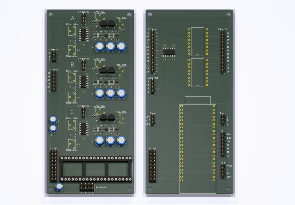
Each Fourays synth needs four of the left hand AY board and one of the right hand control board. That's five boards to assemble together which roughly fits in a desktop enclosure about 25 cm x 14 cm x 6 cm. I've done some preliminary mock ups for this form factor, but haven't settled on anything I like enough to show off yet.
The filters in this design still need a +/- 12V supply. I've bought some modules which apparently convert from 5V to +/- 12V for this purpose, so that I can power this from the USB connection but not tested them yet, and neither do I have the filter circuits to see if they work with the converted voltage levels.
Without Filters
I've also been debating about not including the filters at all (and therefore also removing the mixer circuit and CV DACs). In this case, we can get all four AY chips and the ESP32-S3 on one board. On this board I have also re-instated the Gate outputs. The Gate outputs are simple signals which are active when an oscillator is playing, else inactive. These could be used in a modular synth setup to trigger and sync other modules in time with the oscillators. I could include the Gate outputs also on the version with filters.
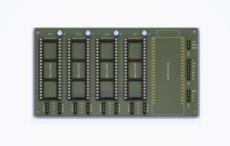
This simpler design would be much more suitable to build as modular synth modules, for example in Eurorack format. This board design would require a module 16HP wide, but is currently significantly too tall, I'd probably have to re-configure this as a pair of boards stacked one behind the other.
But, going down the modular module route presents me with a bit of a conundrum:
Rather than building my own filter and mixer and power supply circuits, should I just make these simple combination boards only, in a Eurorack compatible format? I could then simply just start building a Eurorack synth for myself using the AYs as the core oscillators. That would allow me much more flexibility in how to process the oscillator outputs using any commercially available or DIY euro modules. I could also then just buy a euro case and power supply and the whole thing would be packaged very nicely in a standard format.
But ... that leads to investing in a euro modular system (£££ 🤮), when all I really wanted was some MIDI controlled AYs.
I have in fact already reached the latter goal. I already hand made a combination board for myself on some prototype board. I've repurposed an old enclosure I had laying around which was already fitted with 1/4" jack sockets for the outputs:
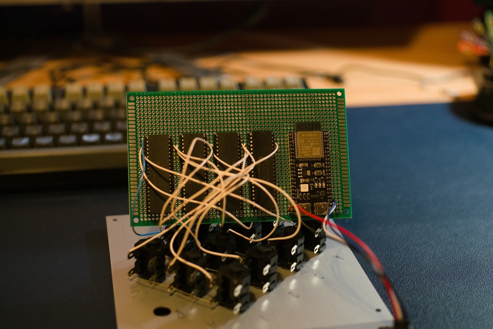
I could stop there and do everything else in software even. But it's not particularly attractive. And, I now have a glut of other chips to build into units, and I know I'm going to either sell or give away those units and those units need to be usable by other musicians, who would probably much rather prefer them to be made to some standard form factor. And I still want to impart a little bit of visual design into this synth to reflect the 1980's era vibes of the old computers which contained these AY chips as their sound generators.
Compiling a Bill of Materials
To see if cost comes into play to help guide me on the form factor decision I decided to do some calculations. Based on the with-filters boards, I submitted my boards to JLCPCB to find out how much they'd cost to manufacture. Also, I needed to work out what other components to purchase to complete each synth, made a list and added up the cost of all of those:
To make all 6 Fourays synths with filters and all the panel controls:
| Item | Cost | Qty | Cost/Item | Qty/Synth | Cost/Synth |
|---|---|---|---|---|---|
| AY boards | £93.08 | 25 | £3.72 | 4 | £14.89 |
| Control board | £21.88 | 10 | £2.19 | 1 | £2.19 |
| Non PCBA components | £152.96 | 6 | £25.49 | 1 | £25.49 |
| Enclosure (TBC) | £5.00 | 1 | £5.00 | 1 | £5.00 |
TOTAL per synth £47.57
That's not bad actually. But it would be significantly cheaper as a Eurorack module, even if the rest of the modular system is likely to be extremely expensive. If anyone has any tips on how to do euro modular on a strict budget, do let me know 😉