Analogue Synthesizer
A box that goes bleep
Ever since starting to make my own gadgets one project that stood out to me as a must-do project was to build a modular analogue synthesizer. Taking this on was no small feat, and took the best part of 5 to 6 years to complete enough to be a mostly usable instrument. Even then, interfacing the synth to a computer DAW took longer still and I have only just recently completed this component.
I took a long time to consider the existing form factors for analogue synths and dismissed them all; mostly due to either cost or because components of those factors would be outside of my ability to make - for example the racks/enclosures commonly used. Putting the final form aside, I started to figure out what modules I wanted and also the bill of materials required to start building them.
I still have no idea about the electronics theory of synth circuits, I have clearly found circuit designs elsewhere to implement. I found a lot of great designs and information at YuSynth back in 2014 and rolled with it as a starting point.
Getting started
From 2014 - 2015 I started assessing which modules I wanted to build. I constructed a huge spreadsheet of modules and components in order to calculate exactly what I would need to purchase for any combination of modules in the synth.
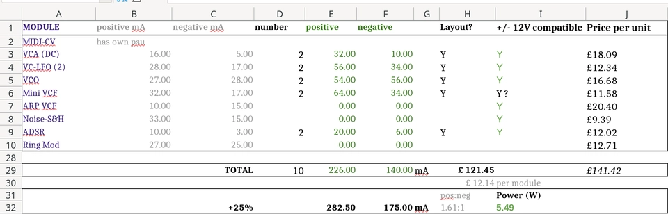
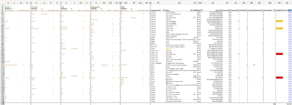
BOM Spreadsheets can be so much fun ?
Using this sheet I reached the point of tedium counting up the number of every type of component in a few different modules and also going to find a source to buy them and figuring out ordering quantities and cost - at which point I elected that the minimum viable synth should consist of:
- One voltage controlled amplifier (VCA)
- One low frequency oscillator (LFO)
- One voltage controlled oscillator (VCO)
- One voltage controlled filter (VCF)
- One ADSR envelope generator (ADSR)
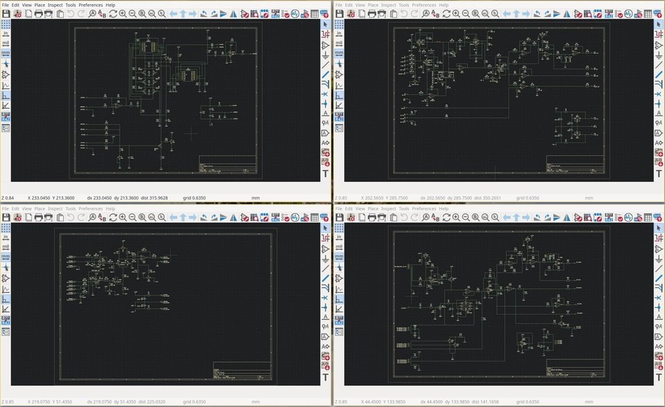
Once I had decided on which modules I was going to build, I started taking YuSynth's circuits and re-making them in KiCAD.

YuSynth's VCLFO #2
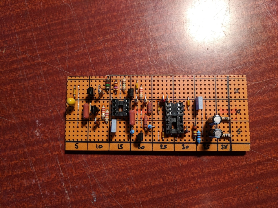
From there I painstakingly used KiCAD to make strip board layouts of the first circuits, since that was all I could comprehend myself doing - make the circuits by hand on strip board. Using a very kludgy workflow of exporting the KiCAD board layers as images and drawing a grid over them in GIMP I eventually started assembling the first circuit.
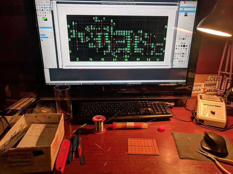
This was pretty seriously tedious work, but I continued to make one circuit and not a lot else. I was getting bogged down with the hand-made-ness of it all and found it hard to keep going when I still had no idea how to assemble all the parts I was lining up to make.

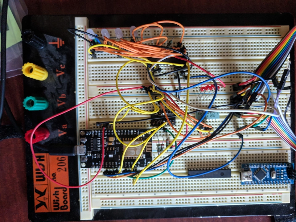
Meanwhile I was also thinking about a digital control module, because for sure want to control the synthesizer from my PC DAW software, as a MIDI device. I prototyped something using an ESP8622, Arduino Nano, MCP4728 DAC and some LEDs. This module will come to be known as psc - more about this later, as the story unfolds I have only recently rebuilt and completed this module to my satisfaction.
The project stagnated around this level of completion for a while in this state. A few other projects came and go in the intervening years, but I was keeping my mind and eyes open for a way to bring this all together.
Enclosure encounter
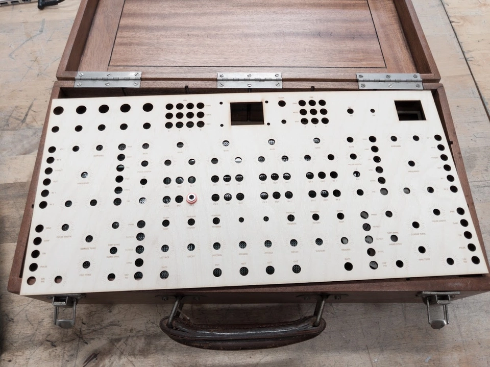
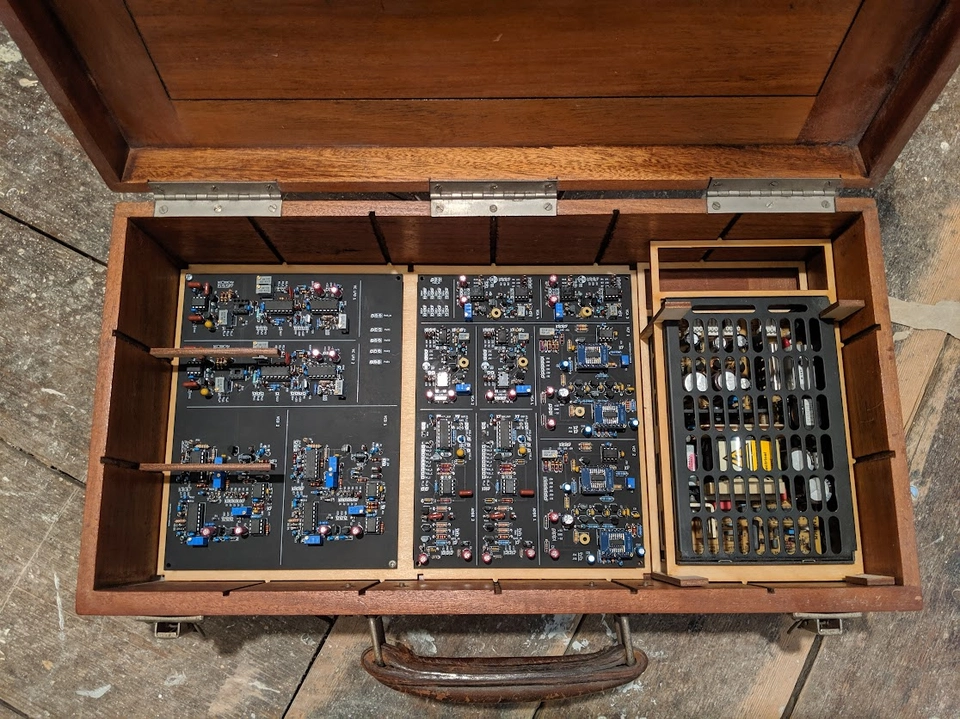
Fast forward to about 2019 and in the course of clearing out a whole load of household junk inherited from my parents, I came across a rather neat wooden box, with latching lid and carry handle which immediately sparked inspiration. It was about the right size to house a good number of synth modules and would also be nicely portable. I don't have any pictures of the box before I started the build, so spoiler alert, here it is with the front panel from the future being test-fitted:
I also happened to find a stack of suitable power supplies, and one provides +12V, -12V, +5V from a mains input; perfect for powering the synth.
Inspired by these finds, I went back to the drawing board to revisit how to construct the circuits.
PCBs might actually be feasible?
I decided I was not going to go through with making all the circuits by hand on strip board. I then came to find out that services such as JLCPCB and PCBWay are actually pretty affordable to the hobbyist maker. Also, I already had the circuit schematics drawn up in KiCAD.
I have no idea how long the process took, but I drew up 2-layer PCBs for all the modules I was going to build. By this time this consisted of:
- 2x VCO
- 2x ADSR
- 2x LFO
- 2x VCF
- 4x VCA
This would provide a 2 voice synth with enough options to get funky with some modulations and filtering. I figured also that more VCAs would be helpful for the psc MIDI control as well.
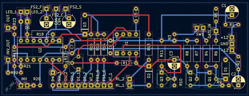
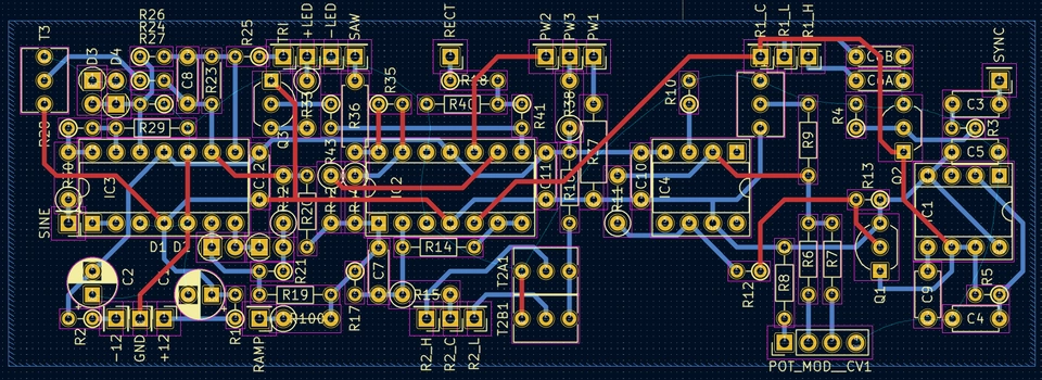
I spent some considerable time adjusting the PCB layouts to be as compact as possible, since getting 12 circuits and a power supply and a psc into this box with through-hole components could end up being a bit of a squeeze.

Compact VCO
Compact ADSR
Compact LFO
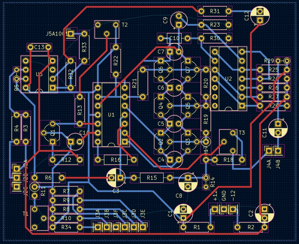
Compact VCF
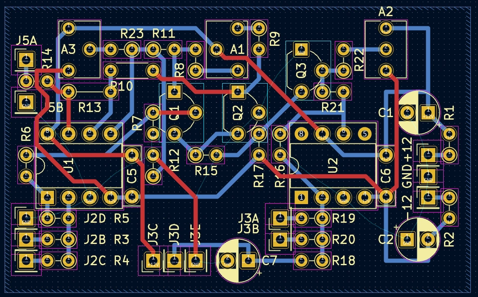
Compact VCA
The next thing to do was figure out how to get these manufactured. I didn't really want to end up with a whole load of different sized boards, and I figured the board mounting would be easier if I could put multiple circuits on one board and have maybe 2 larger boards of the same size.
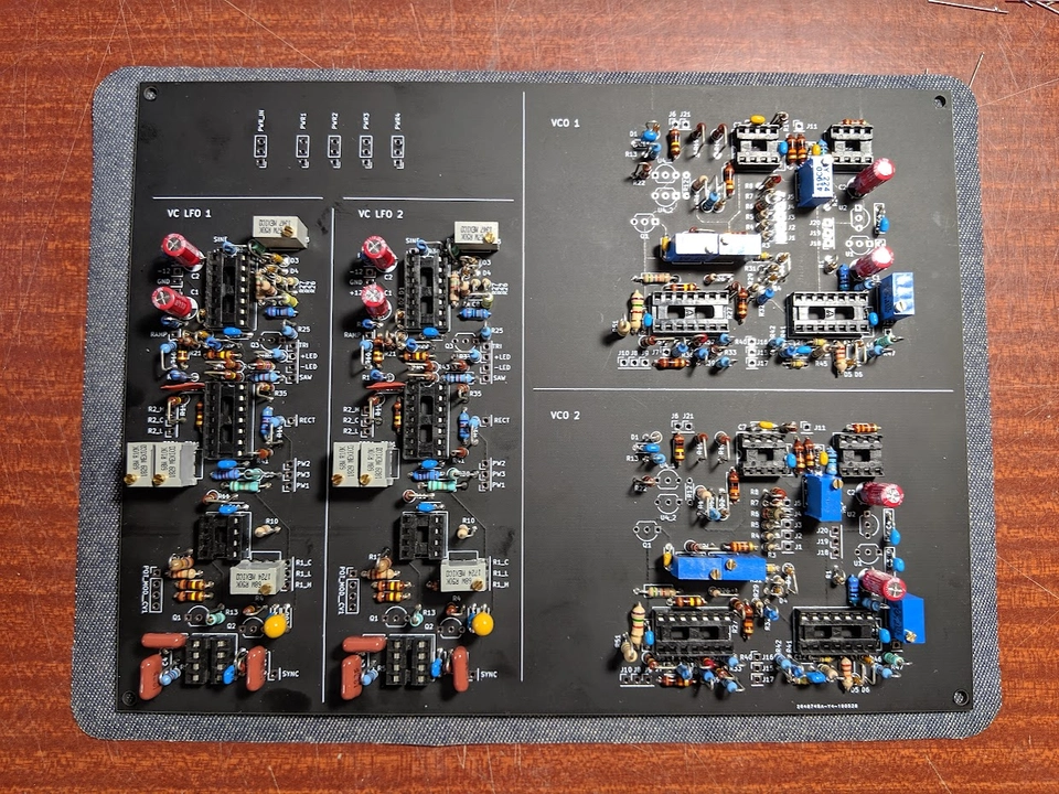
That's actually what I did - I copied the PCB layouts for each module into 2 composite boards of the same size (200mm x 150mm), which would both fit side by side in the enclosure, leaving some space also for a power supply.
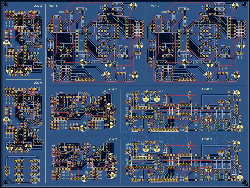

Each module brings the connections to its panel components to named holes, and I also put in some headers to distribute power from the PCB to each module individually. To keep the boards tidy and the circuits isolated I decided that each circuit would be powered with it own headers from flying leads rather than try to route power around the modules on the composite boards.
I sent the files off to JLCPCB and a short while later five sets (the minimum order quantity) arrived even though I only needed 1 of each type. I still have the spares somewhere, let me know if you want a set, I don't plan to make any more of these up (caveat: there's one error I know of on the physical boards. I corrected it in the CAD but I had to cut a track and re-arrange something in the build; I forget exactly what that was though).

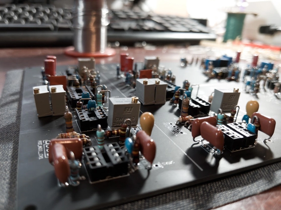
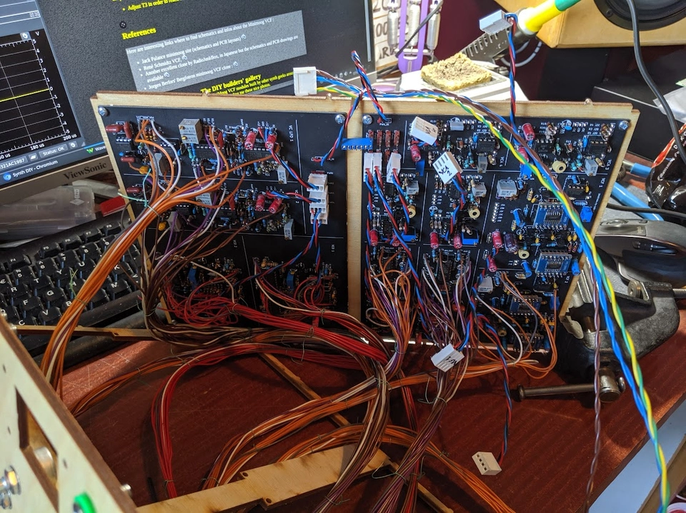
A few days worth of soldering later (and still not completed in these photos):

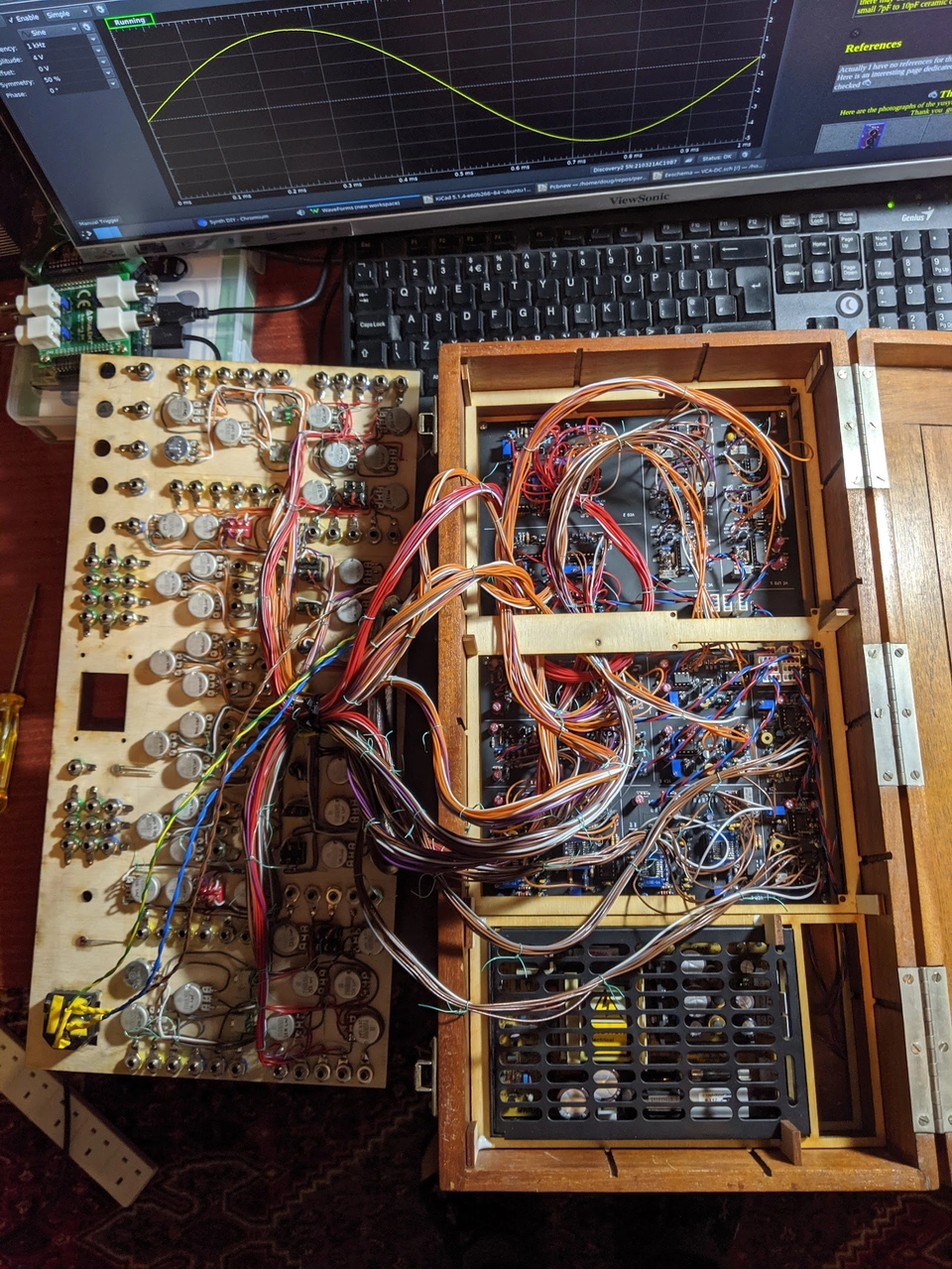
Assembly into the enclosure
During 2019 I was briefly a member of the South London Maker Space and during that time was able to use their laser cutter. I made use of this time to design both the front panel for the synth and also a set of frames to hold the internal components. The frames are designed to be cut from sheet plywood and slot together into a 3-dimensional structure to fill the box and support the other parts. The enclosure itself already had internal grooves cut into the sides, which I have used by leaving bumps on the frame to help keep the frame structure in place.
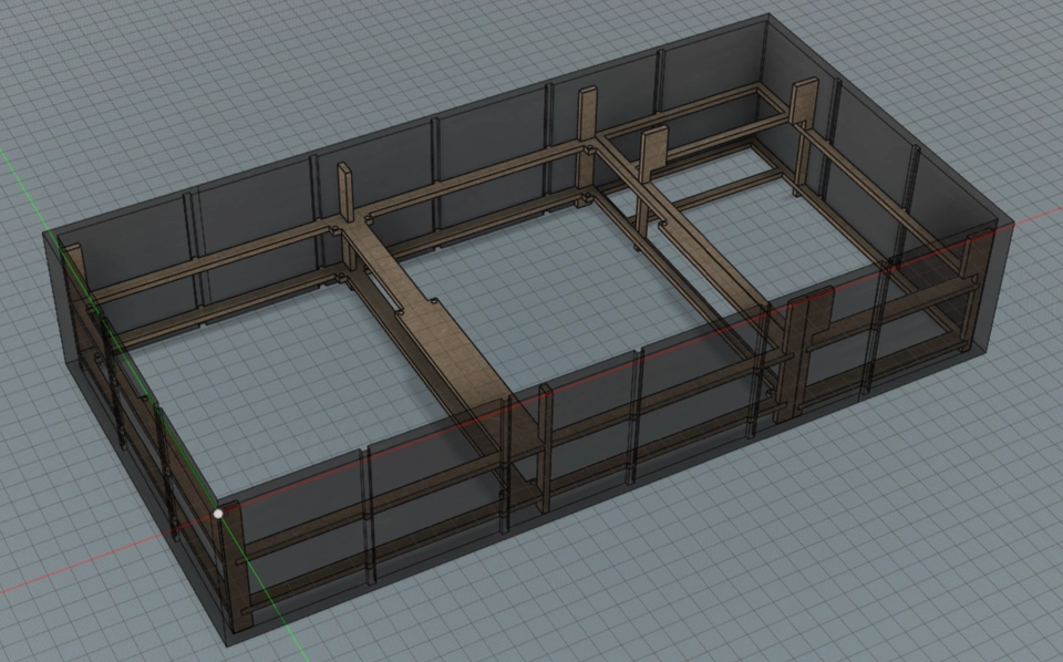
There are two halves to the internal framing. The first is arranged into two decks; the lower one holds the module PCBs and the upper holds the psc board. To the right of that the second frame holds the power supply in place.
Here are the main boards on the lower deck alongside the power supply in the box:
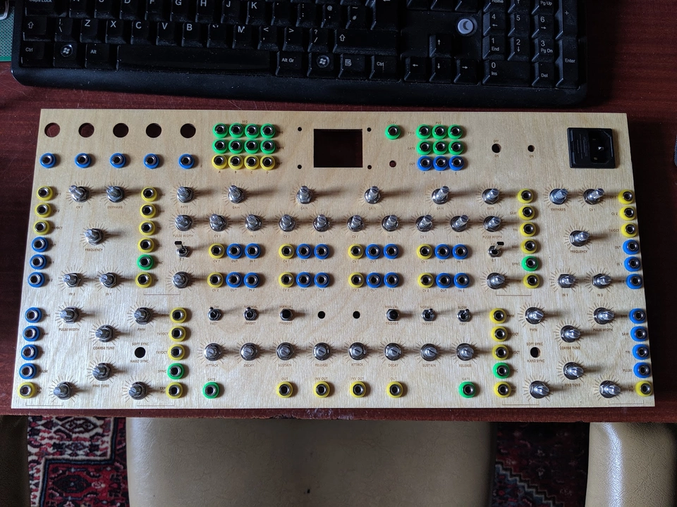
Front panel
Laying out the front panel was a lot of fun. This is the part of the project that lends itself to a bit of creativity and thinking about how the synth will actually be used. Given that this synth has at least 2 of everything, that suggested to me the idea of symmetry.
I took that a little bit to the extreme and made the panel for the synth modules symmetrical down the middle. This means that one voice's worth of modules are on the left and the other on the right - they are mirror images of each other (except for the VCAs). I realise this is unconventional, no other user interface I have ever seen has done this, but on this musical instrument, it works.

The top row of the panel is not symmetrical exactly, as this contains some utility patch points, the psc interface and the power input. The middle row has the modules
[ VCF, LFO, VCA, VCA | VCA, VCA, LFO, VCF ]
and the bottom row has
[ VCO, ADSR | ADSR, VCO ]
Populating the front panel components you can see the symmetry emerging:
On the reverse, starting the panel wiring loom:
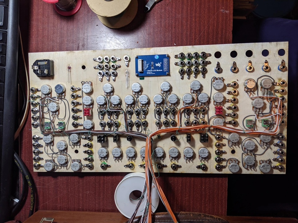
This wouldn't have been possible without colour coded drawings of what each component connects to:

Final assembly
With the frames, PCBs and front panel all ready, it was time to bring it all together.
Wiring panel loom into the boards, with power leads:
Completed module panel wiring and assembly into the box:
If I recall correctly, there's something like over 30m of wire in this thing
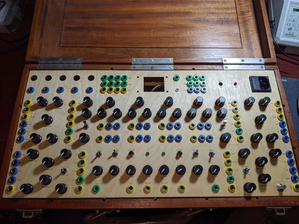
And finally with the front panel fitted with knobs:
Samples?
Erm... OK you got me - to date I still haven't really used this thing for much at all. I will blame this on the lack of a working psc until recently. I also sort of have a history of building devices I don't really use. I should probably stop doing that and also spending 2 days worth of free time simply writing about each project. Or maybe not; a lot of the fun is in the making.
What about the psc ?
This post has got quite long already and psc deserves its own write-up since it went through several iterations both conceptually and physically. You can read more here