My Astrophotography Camera Mount
Originally authored 19 September 2023; subsequently updated:
- 6 October 2023: details of adding motor with gearbox
- 7 October 2023: minor edits for consistency
Intro
In my previous blog post I've talked about my journey into doing astrophotography and how a suitable camera mount is necessary in order to get any sort of reasonable results.
This blog post goes into a fair amount of technical detail of how I went about designing and building my own motorised camera mount for astrophotography.
What is this thing?
I got half way through writing this blog post without actually describing in detail what this mount thing is. So, I've come back up to the top to clarify, the details of how it came to be can follow.
To take pictures of faint objects in the sky, it is necessary to take long exposures. But, because the Earth is rotating, then the camera also needs to rotate so that the motion is cancelled out and the stars remain static points on the image. A second axis of rotation is also required in order to be able to point the camera at any point in the sky.
So, I was going to design a device to which I can attach a camera + lens assembly, which can rotate in 2 perpendicular axes. Initially, it made sense to design the first axis as a turntable going "around" (i.e. parallel to the table top, like a lazy susan) and the 2nd axis on top of that going "up and down" like a swing. So, I am going to make an Altazimuth mount.
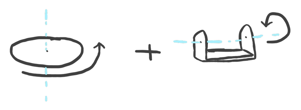
The first "turntable" or "pan" axis is called "Azimuth" and the other is called "Altitude" or sometimes "Elevation". When referring to the mount rotating around these vertical and horizontal axes relative to the Earth's surface I will call them Az/Alt. Later on, when improving how the mount tracks, the mount will be converted into an Equatorial mount and then these axes will be called "Right Ascension" and "Declination" or RA/Dec for short. None of the mount's assembly has changed when we do this, only the names of the directions of rotation.
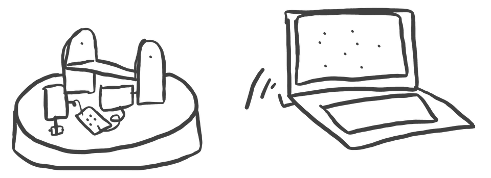
Given that the mount needs to move by itself, it will need at least one motorised axis, so we might as well motorise both of them. Actually, in an Az/Alt configuration it is necessary to move both axes at the same time to compensate for the Earth's rotation. Whereas in an Equatorial configuration only one axis (RA) needs to be moving. To compute these axes rotations, the mount will be connected to a computer. This allows for both slowly tracking objects in the sky and also to direct the camera to an absolute position, so that we don't have to manually locate the objects we want to look at.
Because I am writing this post retro-actively regarding the design and implementation of the mount, you may notice that the images included here are not strictly chronological with regards to how the development happened, but are used to illustrate the points of the text surrounding them.
Inspiration
At first, I didn't really want to have to design anything at all and there are two routes into this:
Just buy something off the shelf, plug in and play
Take a look if anyone else on the internet has designed, built and published details of their mounts or something similar.
The first approach is valid, but at heart I'm an engineer and if you've ever looked at doing anything astronomy related, you'll know that decent kit is really really expensive. By the time you get to reading the end of this post though, you might think I'm mad for not just paying up and having something which performs perfectly for far less investment in time and mental energy. I'll counter that argument by stating that throughout all of this, the journey itself was also a goal I wanted to complete. Plus, (spoiler alert) in the end I actually spent less than an off the shelf mount would have cost and I learned a few things. So, I think I'm still winning.
So, I took the second approach. There are quite a few engineers/makers out there who have designed and built motorised camera mounts. There are some open source designs even for the exact thing I want to make here1. In the end, I was most interested in the mount system designed by "isaac879". This mount was designed specifically for more regular photography and film production, but I felt it most closely matched what I wanted to achieve.
I did look at the CAD and model files provided by Isaac, but realised that he'd designed it around his own camera, and the cameras I have are a different size/ I also didn't need any of the track sliding mechanism either. So in the end I didn't simply use his models and print them out, I went ahead and started my own design but using much of the same concepts.
Design constraints
We're not going to get anywhere on this project without knowing what we want to achieve, and exploring any constraints which need to be considered in the design. Here's some which I am retrospectively listing for the purposes of this blog - to be honest, I can't remember if I knew about all of these when I started.
Physical
Camera properties - obviously the mount needs to be able to hold my cameras, and the cameras need to fit within whatever part of the device supports them. The mount also needs to be strong enough to support the weight of the camera + lens in a variety of orientations without significant sagging or stressing any parts. There will always be some degree of flex however, because it will be made primarily of semi-hollow plastic.
3D Printer dimensions - I only have one printer, which can print parts with dimensions no larger than 220 x 220 x 270 mm.
Positional accuracy - the positional changes required to track the stars across the sky are quite small. I knew that standard stepper motors operate at 1.8 degrees per step, which is far too coarse for use in this project, so the motors should not be directly connected to the axes of rotation. Some gearing is required in the design so that each 1.8 degree step of the motor causes a smaller degree of movement of the mount's axes. The largest acceptable increment on the axes will depend on the lens focal length and the exposure time, so for the time being it is not really possible to put a value on the gear ratios, but it is possible to consider that it needs to be as low as practically possible.
Torque - moving a potentially quite heavy camera and lens assembly around is going to require some physical power. The more torque that is required, then the bigger the motors are required to be and the greater the electrical power is needed to supply to them. Direct driving the axes would be a bad idea not only for accuracy, but using gears to reduce the motion actually proportionally increases the torque applied to the driven part. It might still be able to use small motors, if the drive ratio is low enough. Note that one axis also needs to move the weight of both motors, so bigger motors also requires bigger motors.
Positional stability - as the mount is required to hold the camera in position, the weight of the camera must not be enough to back-drive the mechanism and overcome the available torque of the motors. Even with low drive ratios, it can still be possible to back-drive the motors in this way. Worm gears are less susceptible to being back-driven beyond a certain lead angle; this might be useful for one or more of the axes. Since there will be gears in the mechanisms, backlash or any "play" in the system should also be minimised. This can achieved by ensuring accurate part dimensions, part stiffness and also considering perhaps double-helical or herringbone gears.
Optical alignment - this one is actually not so important for looking at the sky, since any parallax effects do not need to be considered; however if the mount is to be useful perhaps also for normal photography or film making, weird parallax effects can be reduced during rotation by making sure that both axes of rotation of the camera are around a point known as the entrance pupil. I've seen these effects before2.
From a practical point of view, I also wanted the mount to not require too many components which I would have to buy pre-made or would require manufacturing using methods not currently at my disposal; so, no metalwork, woodwork etc.
Software
I was really keen that this project not be a multi-month long software authoring effort. I leave that for the day job - and previously when hobby projects start to get heavy on the software side I tend to get quite tired of the process and that greatly reduces the chances that the project will get finished.
That said, I knew there would need to be some and that would involve also learning about how to drive stepper motors and also how astronomical coordinate systems work.
For the "Go-to" part of the design, where the mount can be told exactly where to point, I wanted to integrate the motor controller with astronomy software. This would allow the astrophotography shooting to be somewhat automated.
Finding good CAD tools
I'm a big fan of using open source software where I can. However, before I started this project I wasn't up to speed on doing 3D engineering CAD at all, let alone with any open source software. I went around the loop trying out what I could find available;
Blender - great for artistic modelling, but good luck doing CAD or engineering design with it3.
FreeCAD - I tried and tried and tried to get into this. It promises so much, but there are two fatal flaws in my opinion. First, the UI is a nightmare. I have no idea which "workbench" I am supposed to be using, and there are so many similar choices available, each with subtly different tools and ... I gave up trying to make sense of it. Secondly, even when following tutorials to get some basic modelling done, I found lack of sensible keyboard control and having to click almost everything a real distraction. Not a good experience.
OpenSCAD - Is an extremely appealing concept; to be able to model by writing code, as if I'm writing software ... but in practice it's quite cumbersome and as stated in the design goals of this project, I wanted to focus on making rather than programming. I have used this before though for some simple box modelling, and even then the code for the model was quite hard to manage.
There are others out there, but by this point I had got fed up with yak shaving and just wanted to get on with the project. So, after all of that, I recalled that I had used Fusion 360 for my modular synth build and it was free to use for personal projects at the time. I thought I had heard at some point they had discontinued the free for personal use tier, but I seem to have been wrong about that. I found my old account, reset password and got back into it. I found my old synth design files in my account still; nice.
I find Fusion 360 very pleasant to use, so I spent a week or so of spare time getting to grips with it and set about drafting up parts for the design.
Physical design details
Following suit from Isaac's design, I established that I should be able to assemble the mount using entirely M3 nuts and bolts. After a few tests, I established the correct bolt and nut sizes to use for my 3D printer and then it is simply the case of making connecting holes in adjacent parts for assembly. I wanted all bolt heads and nuts recessed into parts so that all outer surfaces are flush.

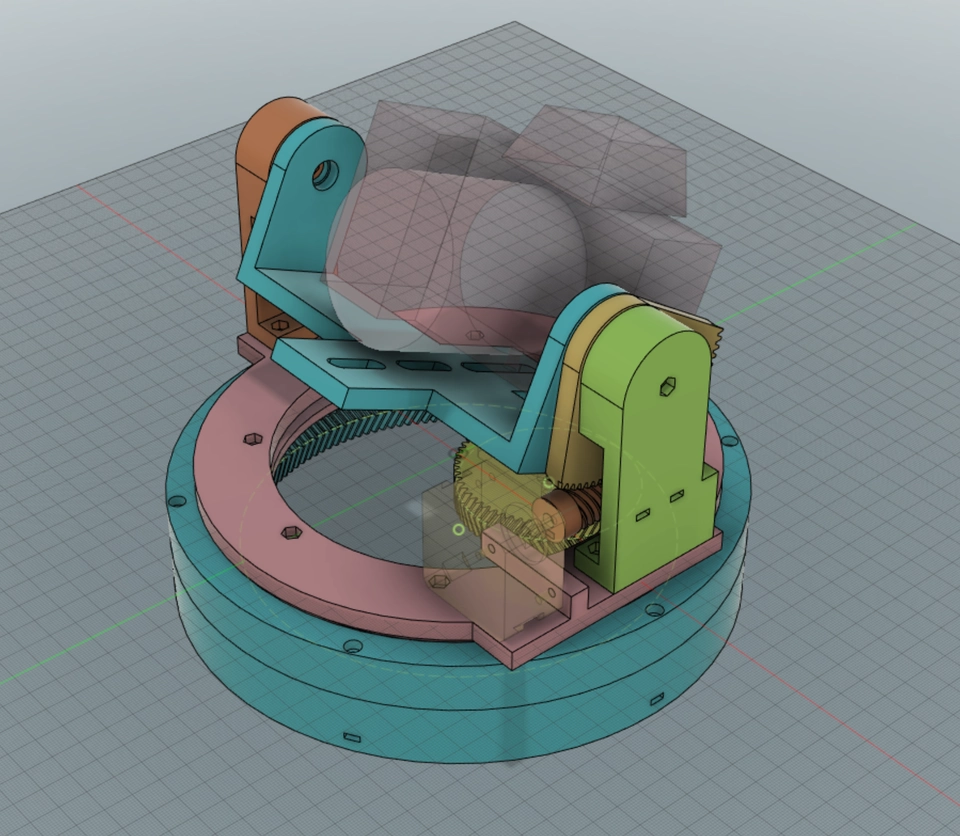
For the Alt/Dec axis I chose a worm drive design. I thought that this axis would be most susceptible to being back-driven due to the weight of the camera and lens. As it turns out, both axes can be susceptible to this, depending on the position. However, the worm drive on this axis does provide a decent reduction ratio for positional accuracy. The design and print tolerance for this gear set though is not so great in the current version, the gears do not mesh completely and there is some backlash on this axis. It is mostly not a problem in practice as the weight of the camera keeps the axis biased to one side, but as it tips over the centre of mass of the camera it introduces positional error. I may come back to re-print one of the gears in this set to improve the meshing, but there also is not a lot of available clearance to make either one much larger.

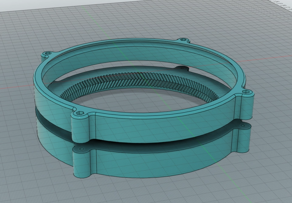
I settled on using herringbone gears for the Az/RA axis. This required a plug-in for Fusion 360 in order to generate the models. I used a modulo of 1 mm for all gears in the design. This proved correct the theorem that herringbone gears reduce backlash, or maybe the design and print tolerances played in my favour here as the Az/RA axis is pretty snug and works well.
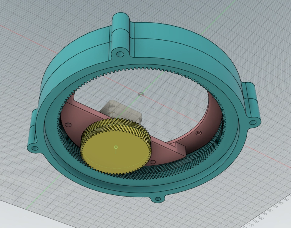
It is worth looking at the actual design for the Az/RA axis and how this part of the mount moves and is held together. I wanted to implement something approximating a large thrust bearing or slew bearing, and not have to buy one as at this size that can get expensive and I honestly don't need the precision of machined metal parts. This type of bearing is designed to support axial load, which is what the design calls for in the "turntable" part. I drew up 3 parts which implement a slewing bearing. The first is the outer base part containing a < shaped slot around the inner circumference. The second two parts combine to form the other matching > slot, and in the slot I fill in with steel ball bearings. These parts are split in order to allow assembly of the bearing, and form the "plate" of the "turntable".


The end result turns well enough, but obviously not as smoothly as a quality metal bearing. There are some inconsistencies in the bearing surfaces which causes some points in the rotation to stick slightly. Some work with a file or sandpaper may improve this, as well as slightly loosening the bolts holding the two inner parts together.
The base itself is printed in two parts to allow for easier assembly of the big bearing and reduce risk in 3D printing such a large part in case of warping or other failure - not to mention reduce the individual part print time, the whole base would otherwise have taken in excess of 15 hours to print in one part.
Learning and using 3D printing
I got my 3D printer back in May 2023, with the intention of making practical useful things with it. I got a Creality Ender 3 S1 Pro. It's a nice machine, mid-range hobbyist type. The first thing I did with it was make some modifications to my Watkins Copicat but this project would be the first "big one".
There are some additional steps needed in order to get the design from CAD and into the real world. It is not possible to directly send the CAD model to the printer, it has to be processed it into something the machine understands, and this process is called "slicing". There are quite a few different slicing software packages available (and some of them share a common history). I tried out just about all that I could find and settled on using PrusaSlicer. Even though this is provided by Prusa primarily for use with their printers, it is open source and has a long lineage in open source 3D printing. There are configurations available out of the box for Creality printers, and I find the software itself nice to use - it exposes settings when you need them, but otherwise keeps out of the way and has sensible defaults. There's a few concepts to get to grips with being successful with slicing, but that's not what this post is really about; just know that I spent also a good few weeks of spare time researching and testing out what the different settings and features are and how they affect the final print.
Throughout this project, I had to ensure that details of the design would work when 3D printed. I was also initially unsure about tolerances required for parts which need to fit inside each other, or mesh against each other. I was also mindful that I didn't want to waste material or printing time (did you know that FFF 3D printing is a somewhat painfully slow process?) by simply committing to print all the parts as-designed and hoping that it would turn out OK. So, for certain aspects of the design such as the bolt holes, captive nut recesses and bearings, I sliced out small sections of parts and printed just those as tests, so that I could establish how good the tolerances are. With some parameter tweaking later, I was confident to go ahead and print the full parts knowing that they would assemble correctly.
Learning and using stepper motors
Considering the requirements for accurate and absolute position of the axes, stepper motors seem to be a good place to start for this project. Stepper motors have a known and accurate amount of rotation per step, and a microcontroller can be used to count out and keep track of the steps provided to the motor. In this way, the mount can always know how many degrees of rotation has been applied to each axis - in other words, no other sensors are required to know where the camera will be pointing.
There is a down-side however - the motors can only move in discrete steps and not in a continuous motion. This presents a bit of an issue for tracking stars with long exposures, the point light of the star will appear to jump in steps across the image instead of being perfectly aligned on one spot. This can be mitigated using a low enough gear drive ratio that each step is within a tolerable limit and also combining with micro-stepping, where the motor can be somewhat held in positions between steps. Using micro-stepping however can reduce the torque provided by the motor, so there are some trade-offs to be made here.
The Az/RA axis needs a very fine resolution of motion in order to ensure that the star points are not spread across the image due to the discrete motion of the stepper motor. To track the Earth's rotation, this axis needs to move at a rate of 0.25 degrees per minute. It is therefore necessary to have quite a large gear reduction ratio on this axis, such that one single step of the motor produces a movement so small that it is not detectable on the image. Therefore, as the motor is periodically stepped, at a high enough reduction ratio the axis is effectively moving continuously. This is technically not true, but in practice is good enough over the duration of a typical exposure. The initial reduction ratio was 63:144 (0.4375) but this was not good enough. I iterated again on the motor for this axis and put in a motor with a 139:1 reduction gearbox integrated; this gives a final drive ratio of 1:139 x 63:144 (0.003147). I also changed out the motor driver chips for slightly better ones which provide 64x micro-stepping. This gives a final resolution of nearly 11300 micro-steps per degree of rotation on the Az/RA axis.
I also didn't want to have to go low-level on the microcontroller software and implement the motor control myself. Taking inspiration from my 3D printer, I realised that the same kind of controller board as is in my printer could be used for the task of controlling this mount. There are already well-established products and control protocols for machines with stepper motors, such as 3D printers or CNC machines.
A good place to start is to get a pre-built CNC controller circuit board and make a mental shift to interpret commands such as "move the Y-axis 30 mm at 2 mm/s" to really mean "rotate the RA-axis 30 degrees at 2 degrees/s". It's a simple case of scaling the "dimensions" to suit the gear ratios and using different units.
Using GRBL, Arduino and CNC shields
The programming language used for CNC machine control is called G-code. 3D printers use some of the same commands, and extend this language for printer-specific features (the job of the slicing software mentioned above is actually to translate a CAD model into G-code). One flavour of CNC G-code language is called grbl and this implementation runs on Arduino devices.
There are also quite a lot of Arduino and grbl compatible motor controller circuit boards available. Some are quite bare-bones, that you have to separately buy an Arduino and the motor driver circuits to plug into it. I tried a couple of different ones, but settled on something very cheap in the end - the advantage of using a plug-in Arduino is that I could be able to modify the grbl software running on it, should I need to. Luckily, so far I have not needed to.
Also, if I goofed up and fried some of the electronics, then each part is separately replaceable and at low cost.
The final electronic module involved is a Bluetooth serial module, which connects to the controller board via power and UART serial pins. Once configured to match the UART speed of the Arduino it can be connected to from a computer at any serial baud rate and it forwards the serial data in both directions.
  graph LR
subgraph C[Controller Board]
A --> M1[Motor Driver<br>TMC2209] & M2[Motor Driver<br>TMC2209]
end
BT[Bluetooth<br>Module] <--> A[Arduino<br>Nano]
M1 --> S1[Stepper Motor]
M2 --> S2[Stepper Motor]
GRBL configuration
Grbl requires a little bit of configuration, with regards to knowing how many steps to apply to a motor in order to reach a certain distance travelled. By starting with the degrees per step and the gear ratios of the axes, I could derive the scaling factors necessary such that the grbl dimensions match the rotation of the axes in degrees.
| Tilt/Alt/Dec | ||||
|---|---|---|---|---|
| 5 | threads | worm | ||
| ÷ | 90 | teeth | driven gear | |
| = | 0.056 | ratio | worm : driven | (1/ratio = 18.000) |
| x | 1.80 | deg/step | stepper input | |
| = | 0.100 | deg/step | driven gear | |
| 1/ = | 10.00 | step/deg | ||
| x | 64.00 | micro-step | ||
| = | 640.000 | step/deg |
| Pan/Az/RA | ||||
|---|---|---|---|---|
| 63 | teeth | drive | ||
| ÷ | 144 | teeth | driven | |
| = | 0.438 | ratio | drive : driven | (1/ratio = 2.286) |
| x | 1.80 | deg/step | stepper input | |
| = | 0.788 | deg/step | drive ratio | |
| 1/ = | 1.27 | step/deg | ||
| x | 64.00 | micro-step | ||
| = | 81.2698 | step/deg | without gearbox | |
| 1 | gearbox | drive | ||
| ÷ | 139 | gearbox | driven | |
| = | 0.0072 | gearbox | ratio | |
| x | 81.2698 | step/deg | without gearbox | |
| = | 11,296.5079 | steps/degree | with gearbox |
These final scaling values need to be configured on the grbl Arduino as the "steps/mm" parameters $100 and $101 respectively. The "Max rate mm/s" also needs to be set in $110 and $111 registers so that the mount moves at a sensible rate when moving between targets. If this rate is too fast, the motors can skip steps either because the mass of the motor stator alone cannot move that fast, or because the mass of the mount and camera and lens cannot be accelerated fast enough. If the motors skip steps, then the mount loses positional accuracy and is no longer pointing in the direction the controller thinks it is. If the motors move too slowly, then the mount would take too long to reach the next target. It is also possible to change the acceleration of the motors in mm/s2 in registers $120 and $121 so that the motors do not try to exceed the available drive power.
ASCOM and custom driver
The next step is to interface the motor controller with the controlling computer. How will the computer tell the camera where to point?
In the first instance, I looked at manually extracting viewing coordinates from Stellarium, as I initially thought that would make the overall system simpler. However, Stellarium does not directly provide the coordinates I required at the time (Az/Alt) over its remote control API. I persevered with this for a while, but it became clear that I would need to implement complicated coordinate conversions myself and that I would also not really be integrating properly with any astronomy software.
During this initial investigation into integration I became aware of ASCOM, which is a standard set of interfaces for astronomy equipment. I also actively avoided going all-in on starting an implementation of an ASCOM Telescope driver ("telescope" is synonymous with "mount" in this context) as I thought that would be another software authoring black hole I'd disappear into.
It quickly transpired that I would not be able to avoid writing this ASCOM Telescope driver; and that the benefits would be quite large. My custom driver would mean that my mount will then work with any astronomy software which also interfaces with ASCOM standards, and I would not be limited to just using only e.g. Stellarium and the equivalent of a string-and-sticky-tape solution.
Writing the driver turned out to be fairly straightforward after studying the templates, documentation and other open source examples. I've not programmed in C# either before, so some learning on that front was also required. Within a week or so I had something which worked, and the ASCOM driver infrastructure took care of all the coordinate conversions using simple API and it is successful in hiding away a lot of complexity.
My driver implements an ASCOM Telescope driver which outputs G-code over a serial connection. The driver is open-source and can be viewed/cloned/forked from here:
https://bitbucket.org/doughammond/ASCOM.PTMount
Further driver development
As I understand it, there is another driver standard called INDI which is supported on platforms other than Windows. I may in the future also implement an INDI driver for this mount, but it is not a priority at the moment.
Testing and Issues
I started using the mount in Az/Alt mode and became quite pleased with a working Go-To and tracking system. The mount keeps the target close enough to the centre of the image such that stacking software is able to combine multiple exposures successfully.
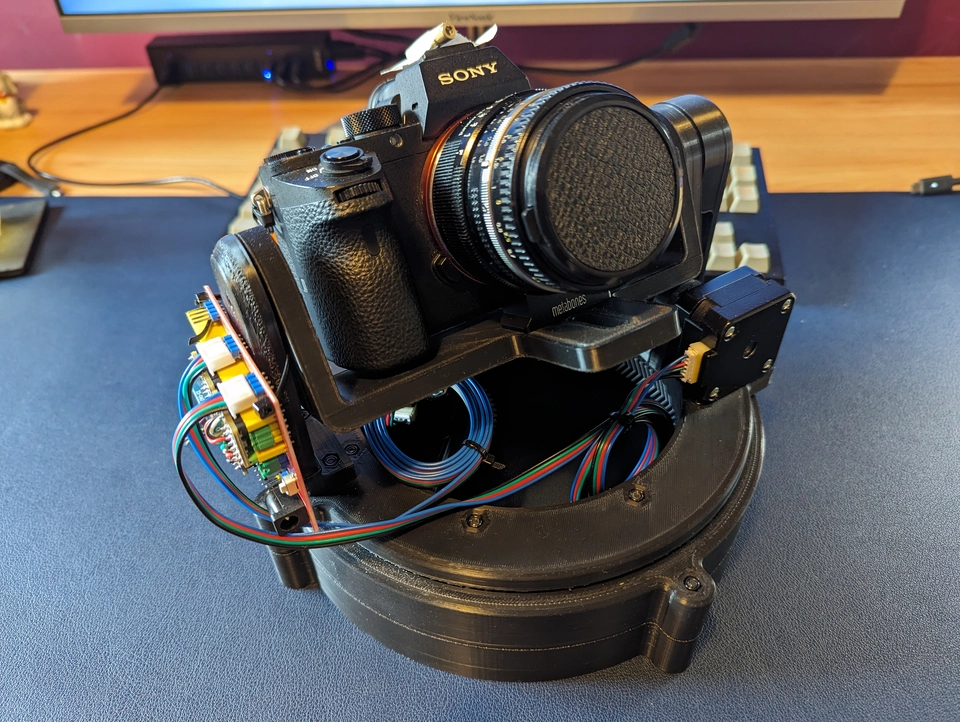
At this point in time, the controller board attachment was still temporary and I was using the first set of motors, the small 26 mm ones. These motors would later struggle with larger lenses and in the Equatorial configuration and I have upgraded them currently to 60 mm motors which are able to provide a much higher torque.
The images I have taken in this configuration did work, but it became apparent that the issue of field rotation in Az/Alt tracking would have an impact on my final images, by reducing the quality of the image away from the centre. The effect of this is that the stars in the image will appear to rotate about the centre over time, and this is a consequence of the Earth's axial tilt.
A minor point related to this also is that these rotation-corrected images have no standard orientation, or rather the final stacked image would have to be manually rotated to match what other astronomers would expect to see - compared to shooting with an Equatorial mount where the "up" direction is always the same and does not need any correction.
I briefly considered how to add a third axis to the mount, which would rotate the camera to compensate, but it turns out there is a much simpler solution.
Still, during this time I got to learn a bit about astronomy software and I have settled on using Stellarium and N.I.N.A. together.
Conversion from Az/Alt to Equatorial
To deal with the issue of the field rotation and also to simplify the tracking to require only one moving axis, it would be best to use an Equatorial mount which aligns to the Earth's rotation. It is possible to make a simple change to the mount to convert it from Az/Alt configuration to Equatorial. This is one of those techniques that if you don't know possible, then you'd not easily be able to discover. I was given a hint to look into the "wedge" solution.
What this entails is to simply place the mount on an inclined wedge platform. The angle of the wedge is related to the observation location's latitude, 90 - latitude. In my case, observing near London, I need a wedge platform angled at about 38.5°. I've 3D printed some supports which assemble to this angle and I'm able to attach the mount using the existing base assembly bolt holes.
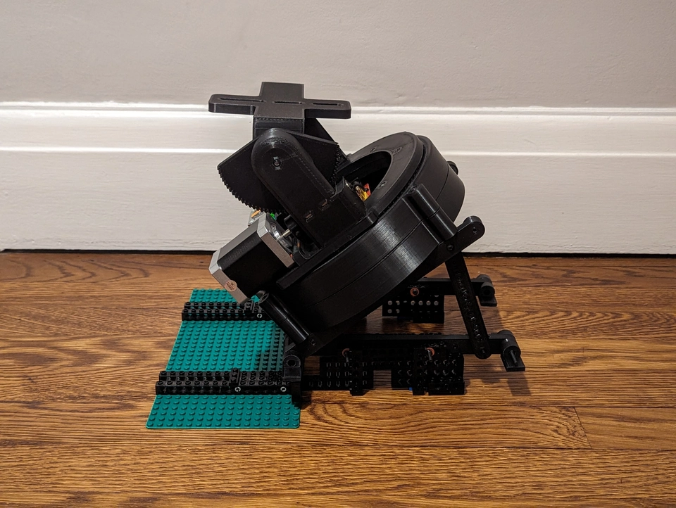
I didn't anticipate the fact that at some positions, the camera and lens centre of mass is over or beyond the lower edge of the mount and it is prone to tipping over. The temporary solution to this is to fix the supports to some Lego which prevents the whole thing tipping. There's a couple of things I could do as a more permanent solution, perhaps:
- Convert the "feet" into fixings with holes so that I can screw/bolt the supports to something fixed; either a plank of wood, or some aluminium extrusion or a table/portable workbench.
- Design and 3D print a better support frame which extends out further to prevent the tipping.
Update: I have indeed now mounted the wedge feet onto aluminium extrusion, this provides a good stable base for the system.
Full sky visibility
With the mount in Equatorial mode and the camera cradle attached in the original "underslung" configuration, and using the original ~100° driven gear for the Dec axis I was not able to position the camera to any part of the sky less than 0° declination. This was a symptom of assuming that I'd be using the mount in Az/Alt originally, where the Altitude axis is only needed to go from 0 to 90 degrees. This is a problem because that rules out actually being able to view a large portion of the sky to the south at this latitude.
Even if I were to print another gear which works in the range of e.g. -50 to +90 degrees almost any negative rotation here would cause the lens to collide with the top of the mount. The cradle would need to be higher in order to provide the necessary clearance.
In the first instance, with the new gear printed, I simply also inverted the camera cradle to an "over-slung" configuration. This was OK to prove a point that it allows the mount to see any part of the sky, but this is not a stable configuration with the original cradle dimensions. More about this below.

Torque
You might have gathered from reading all of the above that I underestimated the power required to move even a moderately sized camera and lens assembly. I initially bought NEMA 17 26 mm motors thinking that the small and lightweight size would be beneficial. It turns out they are more than a bit on the wimpy side. Especially in Equatorial mode, the angles at which the camera is held seem to put more of a strain on the axes and the only solution is more power.
Motor iterations & current & heat
As of the time of writing I have replaced the Alt/Dec 26 mm motor with a 60 mm motor and the Az/RA motor with a 40 mm motor + 139:1 reduction gearbox. The alt/Dec axis has enough torque now to keep the axis in place, and there's enough reduction on the Az/RA axis that it is not possible to back-drive it at all. This seems to provide enough power now to move all the camera and lens combinations I have tried so far. The largest being a Nikon 80-200 mm f/2.8 zoom lens which is really pretty bulky.
There is a downside to this though. As the motors output more power, then the motor drivers and power supply must also pass more power into the motors. This caused the drivers to get quite hot, but I believe they are still operating within the designed limits. I further adjusted the driver configurations to reduce the current supplied to the motors, enough that I get the torque that I need, but not so much that everything gets hot.
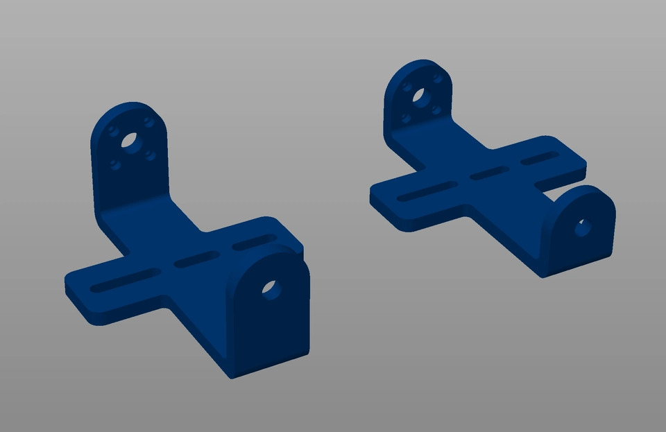
Cradle height
One factor affecting the torque requirements is how far the camera and lens centre of mass is away from the axes of rotation. In the first adaptation of the mount from Az/Alt to Equatorial I simply inverted the camera cradle component, which elevates the camera some distance away from the axes.
Since torque is defined as force times distance, then any excess distance results in increased torque requirements. I went back to the CAD and made a second iteration of the camera cradle which reduces the off-axis distance and therefore reduces the torque required to keep the camera and lens in position. I made this cradle just high enough to be able to level off at the horizon when facing south at my latitude when mounted in the "over-slung" configuration.
Make one yourself?
I have published the 3D models for all the parts of this build here in the same repository as the ASCOM driver code:
https://bitbucket.org/doughammond/ascom.ptmount/src/master/3D%20Print%20Parts/
I would advise however to measure the parts and make sure it's suitable for your camera and 3D printer before starting. You may well find that you will need to make adjustments for your own requirements.
Conclusion
This project is still very much a work in progress if I'm honest, since I'm relatively new to astronomy and I haven't mastered at all the image exposure and stacking process. I've done a few tests but I wasn't happy with the results, and a lot of the exposures were not usable.
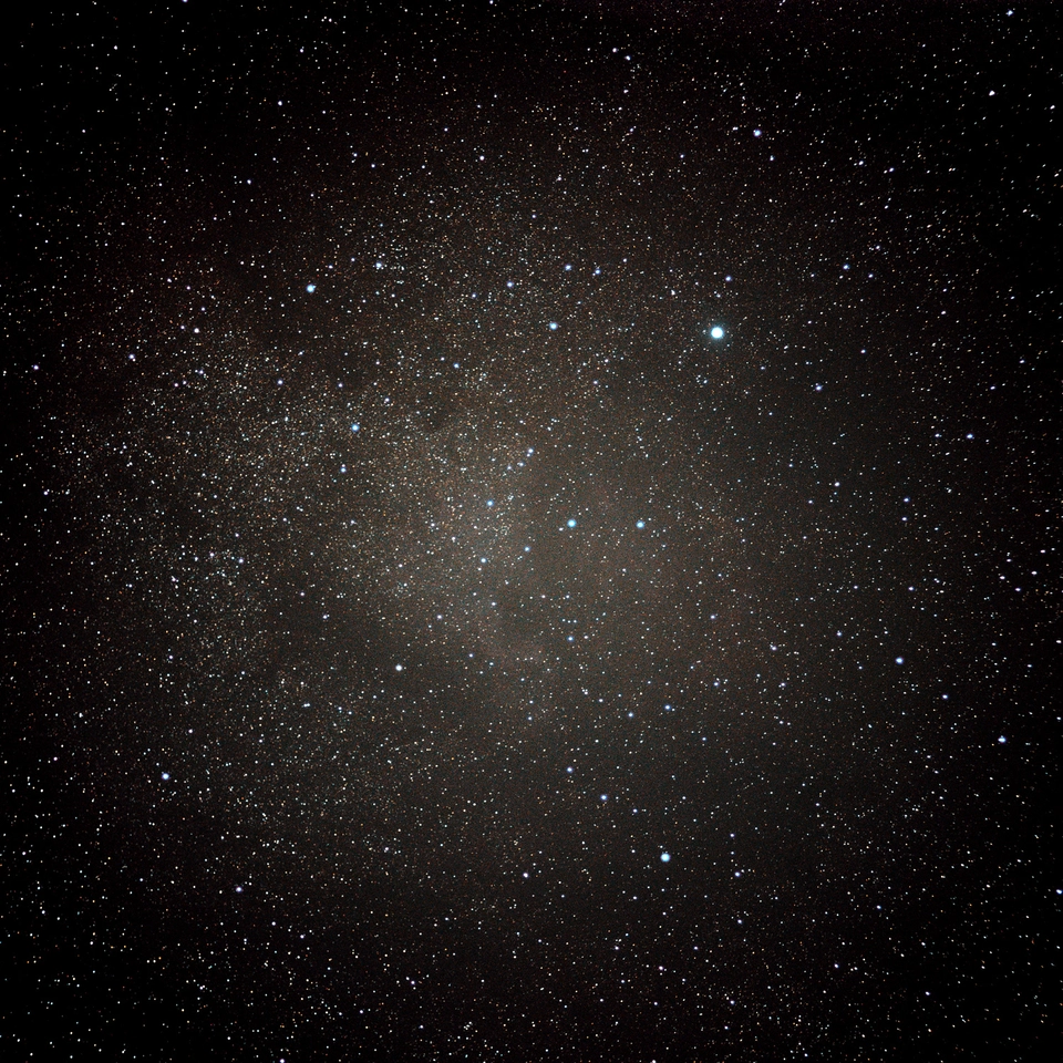
This means that at present, there is no satisfying pay off of being able to show lots of pretty pictures of space objects. But I do have just one faint image of the North America Nebula:
I am keen to keep on with this though, I hope that in the near future the focus will change from fixing and improving the mount to spending a lot more time actually using it for astrophotography. I plan to follow up with further posts on this subject if I can get to a point where I can produce good results.
Bill of Materials
Here's a complete list of materials used in both the design and implementation of this project. Not all of these are needed in the final build, but even so including the parts I did not finally use the total cost was way less than an off the shelf product.
In this table, "Total Qty" is the total quantity of items I actually ordered, and "Parts Cost" is the sub-total for that quantity. "Build Qty" is the quantity actually used in the current design, and "Build Cost" is the sub-total for the quantity used. So, you can see I over-ordered most components (some only come in large multiples), and also iterated on some parts to find ones with better performance (e.g. stepper motors). I originally thought I would implement hall sensors and magnets for automatic homing, but this has not made it into the design at this point.
The counts of nuts and bolts used here is a bit approximate since I don't want to disassemble the mount to make exact counts. Some bolts were also trimmed down to be flush from their original length. Given the bulk nature of the quantities of these, it doesn't affect the build cost if I say I used 10 or 40. Its worth having a range of sizes on hand if you're a hobbyist engineer in any case and you can select the correct bolt lengths during assembly.
The quantity of printer filament used also reflects usage for test parts and re-designed parts that were discarded and are not part of the working mount. This may have been a little less than stated, I haven't weighed what is left, but it looks like much less than half of the spool.
| Item | Qty/Pk | Pks | Total Qty | Price/Pk | Parts Cost | Build Qty | Build Cost |
|---|---|---|---|---|---|---|---|
| F6233ZZ flange bearing | 10 | 1 | 10 | £2.87 | £2.87 | 4 | £1.15 |
| Arduino Nano | 1 | 1 | 1 | £2.82 | £2.82 | 1 | £2.82 |
| HC-06 BT module | 1 | 1 | 1 | £2.49 | £2.49 | 1 | £2.49 |
| CNC Shield | 1 | 1 | 1 | £2.30 | £2.30 | 1 | £2.30 |
| NEMA 17 x 60mm Motor | 1 | 2 | 2 | £11.79 | £23.58 | 1 | £11.79 |
| NEMA 17 x 40mm + Gearbox | 1 | 1 | 1 | £7.97 | £7.97 | 1 | £7.97 |
| TMC2209 stepper drivers | 5 | 1 | 5 | £12.37 | £12.37 | 2 | £4.95 |
| 6.35mm Ball Bearings | 1000 | 1 | 1000 | £9.99 | £9.99 | 150 | £1.50 |
| M3 Nylock nuts | 1000 | 1 | 1000 | £12.63 | £12.63 | 30 | £0.38 |
| M3 square nuts | 50 | 1 | 50 | £0.91 | £0.91 | 6 | £0.11 |
| M3 x 40mm bolts | 50 | 2 | 100 | £2.79 | £5.58 | 17 | £0.95 |
| M3 x 20mm bolts | 50 | 2 | 100 | £1.76 | £3.52 | 8 | £0.28 |
| M3 x 16mm bolts | 50 | 2 | 100 | £1.59 | £3.18 | 6 | £0.19 |
| M3 x 12mm bolts | 50 | 2 | 100 | £1.30 | £2.60 | 1 | £0.03 |
| M3 x 8mm bolts | 50 | 2 | 100 | £0.96 | £1.92 | 7 | £0.13 |
| 3D Printer filament | 1000 (g) | 1 | 1000 (g) | £20.00 | £20.00 | 600 (g) | £12.00 |
| M3 x 6mm bolts | 50 | 2 | 100 | £0.90 | £1.80 | 0 | £0.00 |
| M3 x 4mm bolts | 50 | 2 | 100 | £0.96 | £1.92 | 0 | £0.00 |
| 6mm Ball Bearings | 50 | 1 | 50 | £2.61 | £2.61 | 0 | £0.00 |
| 3x1.5mm magnets | 100 | 1 | 100 | £1.55 | £1.55 | 0 | £0.00 |
| 6x1.5 mm magnets | 50 | 1 | 50 | £2.91 | £2.91 | 0 | £0.00 |
| NEMA 17 x 26mm Motor | 1 | 3 | 3 | £6.01 | £18.03 | 0 | £0.00 |
| HC-05 BT module | 1 | 1 | 1 | £1.45 | £1.45 | 0 | £0.00 |
| GRBL Shield + Motor drivers | 1 | 1 | 1 | £25.66 | £25.66 | 0 | £0.00 |
| A3144E Hall Effect Sensor | 10 | 1 | 10 | £0.57 | £0.57 | 0 | £0.00 |
| TOTALS | £158.86 | £49.04 |
For example OpenAstroTracker - this looks awesome BTW, and I may one day actually make one of these. But, as a project it is quite ambitious, and a bit more than I wanted to take on at this point. However, having completed this project, I will take another serious look at this.
I happen to know this from experimenting with shooting and stitching large panoramas on DSLR some years ago, and I have a manually operated Az/Alt mount for cameras which assists in doing this with the proper entrance pupil alignment - this ensures that when you stitch images together, that all objects in adjacent shots are in the same place and have not moved relative to each other due to the rotation. This type of mount isn't useful for astrophotography though.
I only became aware of CAD Sketcher after I completed this project. I will try it out, but for now, I have committed to using something else.